Download
1 / 26
260 likes | 450 Views
Fine-Grained Latency and Loss Measurements in the Presence of Reordering. Myungjin Lee , Sharon Goldberg, Ramana Rao Kompella , George Varghese. Trend toward low-latency networks. Low latency: one of important metrics in designing a network

E N D
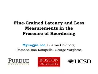
Fine-Grained Latency and Loss Measurements in thePresence of Reordering Myungjin Lee, Sharon Goldberg, RamanaRaoKompella, George Varghese
Trend toward low-latency networks • Low latency: one of important metrics in designing a network • Switch vendors introduce switches that provide low latency • Financial data center begins to demand more stringent latency
Benefits of low-latency networks • An automated trading program can buy shares cheaply • A cluster application can run 1000’s more instructions Content Provider Brokerage Financial Service Provider Network Our network provides E-to-Elatency SLA of a few μseconds Low latency
But… • Guaranteeing low latency in data centers is hard • Congestion needs to be less than a certain level • Reason 1: No traffic models for different applications • Hinders managers from predicting offending applications • Reason 2: New application’s behavior is often unforeseen until it is actually deployed • E.g., TCP incast problem [SIGCOMM ’09]
Latency & loss measurements are crucial • Need latency & loss measurements on a continuous basis • Detect problems • Fix: re-routing offending application, upgrading links, etc. • Goal: Providing fine-grained end-to-end aggregate latency and loss measurements in data center environments Content Provider Brokerage A B E-to-E latency and loss measurements
Measurement model • Out-of-orderpacket delivery due to multiple paths • Packet filtering associates packet stream between A and B • Time synchronization: IEEE 1588, GPS clock, etc. • No header changes: Regular packets carry no timestamp Content Provider Brokerage Financial Service Provider Network A B … Multiple paths Brokerage Filter Filter Out-of-order delivery
Measurement model • Interval message: A special ‘sync’ control packet to mark off a measurement interval • Injected by measurement modules at an edge (e.g., Router A) • Measurement interval: A set of packets ‘bookended’ by a pair of interval messages Router B Router A Content Provider Brokerage Financial Service Provider Network A B Filter Filter Measurement Interval Interval Message Interval Message
Existing solutions • Active probes • Problem: Not effective due to huge probe rate requirement • Storing timestamps and packet digests locally • Problem: Significant overhead for communication • Packet sampling: Trade-off between accuracy and overhead • Lossy Difference Aggregator (LDA) [Kompella, SIGCOMM ’09] • State-of-the-art solution with FIFO packet delivery assumption • Problem: Not suitable in case where packets can be reordered
LDA in packet loss case • Key point: Only useful buckets must be used for estimation • A useful bucket: a bucket updated by the same set of packets at A and B • Bad packets: lost packets to corrupt buckets X Router B Router A 7 2 1 5 11 3 9 Hash Hash Bucket Packet count Corrupted bucket Timestamp sum (3 – 1) + (9 – 5) + (11 – 7) True delay = 3 = 3 Estimated delay = Interval Message = 3.3 Estimation error = 9% 2 2 2 1 1 1 1 12 – 6 11 2 9 1 12 3 6 2
LDA in packet loss + reordering case Freeze buckets Freeze buckets after update • Problem: LDA confounds loss and reordering • Packet count match in buckets between A and B is insufficient • Reordered packets are also bad packets • Significant error in loss and aggregate latency estimation X Router B Router A 7 1 5 2 3 9 11 13 Reordering Hash Hash No reordering Packet count Timestamp sum True delay = 3.3 Estimation error = 59% = 5.25 Estimated delay = 1 2 1 1 2 1 2 2 12 + 24 – 6 – 9 3 1 11 9 2 6 24 12 4 True delay = 3.3
Quick fix of LDA: per-path LDA • Let LDA operate on a per-path basis • Exploit the fact that packets in a flow are not reordered by ECMP • Issues • (1) Associating a flow with a path is difficult • (2) Not scalable: potentially need to handle millions of separate TCP flows
Packet reordering in IP networks • Today’s trend • No reordering among packets in a flow • No reordering across flows between two interfaces • New trend: Data centers exploit the path diversity • ECMP splits flows across multiple equal-cost paths • Reordering can occur across flows • Future direction: Switches may allow reordering within switches for improved load balancing and utilization • Reordering-tolerant TCP for use in data centers
Proposed approach: FineComb • Objective • Detect and correct unusable buckets • Controlthe number of unusable buckets • Key ideas • 1) Incremental stream digests: Detect unusable buckets • 2) Stash recovery: Make corrupted buckets useful by correction • 3) Packet sampling: Control the number of bad packets included
Incremental stream digests (ISDs) • An ISD = H(pkt1) H(pkt2) … H(pktk) • is an invertible commutative operator (e.g., XOR) • Property 1: Low collision probability • Two different packet streams hash to different value • Allows to detect corrupted buckets • Property 2: Invertibility • Easy addition/subtraction of a packet digest from an ISD • The basis of stash recovery
ISDs handles loss and reordering • ISDs detects corrupted buckets by loss and reordering • Buckets are usable only if both packet counts and ISDs match each other between A and B X Router B Router A 06 04 03 2A 03 10 06 2A Hash Hash ISDs don’t match 04 03 03 09 2E 09 2A 3A Hash value 2 1 1 1 1 2 2 2 11 9 24 12 3 2 1 6 Packet count Timestamp sum ISD True delay = 3.3
Latency and loss estimation • Average latency estimation Router A Router B 2 2 3 2 2 1 Packet count 6 9 9 12 24 19 Timestamp sum 09 2E A1 09 3A 9C ISD Delay sum = (12 – 6) + (0 – 0) + (0 – 0) = 6 Count = = 2 2 + 0 + 0 Average latency = 3.0 • Loss estimation Loss count sum = (2 – 2) + (2 – 2) + (3 – 1) = 3 Total packets = = 7 2 + 2 + 3 Loss rate = 0.43
Stash recovery • Stash: A set of (timestamp, bucket index, hash value) tuple of packets which are potentially reordered • (-) stash • Contains packets potentially added to a receiver (Router B) • In recovery, packet digests are subtracted from bad buckets at a receiver • (+) stash • Contains packets potentially missing at a receiver (Router B) • In recovery, packet digests are added to bad buckets at a receiver
Stash recovery • A bad bucket can be recovered iff reordered packets corrupted it • Reordered packets are not counted as lost packets Increase loss estimation accuracy 2 2 12 1 3 34 5 1 1 2 2 2 32 5 1 5 1 1 1 29 2 2 5 1 3A 2E 3E 10 04 2E 04 04 04 10 10 10 ISDs don’t match ISDs match (–) Stash in B A bucket in A A bucket in B All subsets { } – { } { }
Sizing buckets and stashes • Known loss and reordering rates • Given a fixed storage size, we obtain the optimal packet sampling rate (p*) • We provision stash and buckets based on the the p* • Unknown loss and reordering rates • Use multiple banks optimized for different set of loss and reordering rate Details can be found in our paper
Accuracy of latency estimation Packet loss rate = 0.01%, #packets = 5M, true mean delay = 10μs Average relative error 1000x difference Reordering rate FineComb: ISD+stash, FineComb-: ISD only
Accuracy of loss estimation Packet loss rate = 0.01%, #packets = 5M Average relative error Stash helps to obtain accurate loss estimation Reordering rate
Summary • Data centers require end-to-end fine-grain latency and loss measurements • We proposed a data structure called FineComb • Resilient to packet loss and reordering • Incremental stream digest detects corrupted buckets • Stash recovers buckets only corrupted by reordered packets • Evaluation shows FineComb achieves higher accuracy in latency and loss estimation than LDA
Microscopic loss estimation Average relative error Reordering rate
Handling unknown loss & reordering rates Average relative error Reordering rate LDA: 2-banks, FineComb: 4-banks with same memory size