Download
1 / 51
510 likes | 794 Views
Precession Diffraction: The Philospher’s Stone of Electron Crystallography?. Focus. Many methods exist for obtaining diffraction information Selected Area Nanodiffraction and variants CBED All are complicated to interpret

E N D
Precession Diffraction: The Philospher’s Stone of Electron Crystallography?
Focus • Many methods exist for obtaining diffraction information • Selected Area • Nanodiffraction and variants • CBED • All are complicated to interpret • Reciprocal space is right, but intensities depend upon thickness, tilt etc
What PED can do • We would like a method where not just the positions of the spots, but also the intensities could be used. • Not rigorously equivalent to simple kinematical diffraction, but has many similarities • If the structure factor is large Intensity is large • Useful for fingerprinting structures • Often does not need calculations to interpret
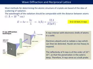
e- e- History – Electron Precession (1993) Advantages:
Scan Non-precessed Precessed De-scan Specimen (Ga,In)2SnO5Intensities 412Å crystal thickness Conventional Diffraction Pattern Precession Diffraction Pattern Precession… (Diffracted amplitudes)
PrecessionSystem US patent application: “A hollow-cone electron diffraction system”. Application serial number 60/531,641, Dec 2004.
SPINNING STAR : UNIVERSAL INTERFASE FOR PRECESSION ELECTRON DIFFRACTION FOR ANY TEM ( 120 -200 -300 KV ) • Can be easily retrofitable to any TEM 100- 300 KV • precession is possible for any beam size 300 - 50 nm • Precession is possible for a parallel or convergent beam • precession eliminates false spots to ED pattern that belong to dynamical contributions • precession angle can vary continuously (0°-3°) to observe true crystallographic symmetry variation • Software ELD for easy quantification of ED intensities and automatic symmetry ( point, space group ) research • Easily interfaced to electron diffractometer for automatic 3D structure determination
Examples: • Complicated Structures • Hard to interpret SAED • Simple to interpret PED • EDS • Elemental ratio’s depend upon orientation in standard mode • Weak to no dependence with PED
APPLICATION : FIND TRUE CRYSTAL SYMMETRY PRECESSION ON PRECESSION OFF IDEAL KINEMATICAL (111) UVAROVITE (111) Courtesy M.Gemmi Univ of Milano
APPLICATION : PERFECT CRYSTAL ORIENTATION PRECESSION ON OLIVINE PRECESSION OFF Crystals –specially minerals -usually grow in platelet or fiber shape and results dificult to orient perfectly in a particular zone axis; in this example olivine crystals are perfectly oriented after precession is on. Courtesy X.Zou, S.Hovmoller Univ Stockholm
EDS, on zone (SrTiO3) Repeat Measurements
Practical Use • Two commercial systems (one hardware, another software) are available • Not complicated, and could probably be written in scripting language • Alignment can be tricky – it always is • Not rocket science, to use
Some Practical Issues Projector Spiral Distortions (60 mRad tilt) Bi-polar push-pull circuit (H9000)
e- e- Block Diagram ‘Aberrations’
Better Diagram Postfield Misaligned Remember the optics Idealized Diagram Scan Objective Prefield Sample Objective Postfield Descan
Remember the optics Idealized Diagram Correct Diagram Both Misaligned Scan Objective Prefield Sample Objective Postfield Descan
Why? • Although PED has been around since 1992, and very actively used for ~10 years (mainly in Europe), there is no simple explanation (many have tried and failed) • Explanation is a bit rocket science
Why? • What, if any generalizations can be made? • Role of Precession Angle • Systematic Row Limit • Importance of integration • Phase insensitivity • Important for which reflections are used • Fast Integration Options
Scan Specimen De-scan k+s k s sz g 0 (Diffracted amplitudes) Ewald SphereConstruction z
Levels of theory • Precession integrates each beam over sz • Full dynamical theory • All reciprocal lattice vectors are coupled and not seperable • Partial dynamical theory (2-beam) • Consider each reciprocal lattice vector dynamically coupled to transmitted beam only • Kinematical theory • Consider only role of sz assuming weak scattering • Bragg’s Law • I = |F(g)|2
Early Models Iobs depends upon |F(g)|, g, f (precession angle) which we “correct” to the true result Options: 0) No correction at all, I=|F(g)|2 1) Geometry only (Lorentz, by analogy to x-ray diffraction) corresponds to angular integration 2) Geometry plus multiplicative term for |F(g)|
100 Å; R=0.25 50 Å; R=0.19 3.2 Å; R=0.02 800 Å; R=0.88 400 Å*; R=0.78 200 Å; R=0.49 Bragg’s Law fails badly (Ga,In)2SnO5
Kinematical Lorentz Correction I(g) =ò |F(g) sin(ptsz)/(psz) |2 dsz sz taken appropriately over the Precession Circuit t is crystal thickness (column approximation) f is total precession angle I(g) = |F(g)|2L(g,t,f) K. Gjønnes, Ultramicroscopy, 1997.
Kinematical Lorentz correction:Geometry information is insufficient Fcorr Fkin Need structure factors to apply the correction!
Limits: Ag small; Idyn(k) µ Ikin(k) Ag large; Idyn(k) µÖIkin(k) = |Fkin(k)| But… This assumes integration over all angles, which is not correct for precession (correct for powder diffraction) 2-Beam (Blackman) form
Blackman+Lorentz Comparison with full calculation, 24 mRad Angstroms Alas, little better than kinematical
Two-Beam Form I(g) = ò |F(g) sin(ptseffz)/(pseffz) |2 dsz sz taken appropriately over the Precession Circuit szeff = (sz2 + 1/xg2)1/2 Do the proper integration over sz (not rocket science)
Two-Beam Integration: Ewald Sphere Small (hkl) Medium (hkl) Large (hkl)
100 Å;R=0.24 3.2 Å; R=0.02 50 Å; R=0.19 800 Å; R=0.67 400 Å*; R=0.62 200 Å; R=0.44 2-Beam Integration better
Some numbers R-factors for kinematical model R-factors for 2-beam model See Sinkler, Own and Marks, Ultramic. 107 (2007)
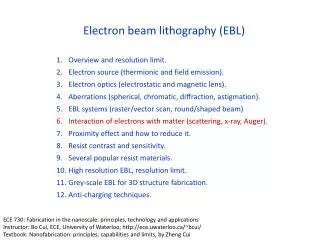
“Conventional”multislice (NUMIS code, on cvs) Integrate over different incident directions 100-1000 tilts f = cone semi-angle 0 – 50 mrad typical t = thickness ~20 – 50 nm typical Explore: 4 – 150 nm g = reflection vector |g| = 0.25 – 1 Å-1 are structure-defining 2f t Fully Dynamical: Multislice
Multislice Simulation Multislice simulations carried out using 1000 discrete tilts (8 shown) incoherently summed to produce the precession pattern1 • How to treat scattering? • Doyle-Turner (atomistic) • Full charge density string potential -- later 1 C.S. Own, W. Sinkler, L.D. Marks Acta Cryst A62 434 (2006)
Multislice Simulation: works (of course) R1 ~10% without refinement of anything
Global error metric: R1 • Broad clear global minimum – atom positions fixed • R-factor = 11.8% (experiment matches simulated known structure) • Compared to >30% from previous precession studies • Accurate thickness determination: • Average t ~ 41nm (very thick crystal for studying this material) (Own, Sinkler, & Marks, in preparation.)
Quantitative Benchmark:Multislice Simulation Bragg’s Law Absolute Error = simulation(t) - kinematical Error thickness g 10mrad 24mrad 0mrad 75mrad 50mrad Experimental dataset (Own, Sinkler, & Marks, in preparation.)
Partial Conclusions • Separable corrections fail; doing nothing is normally better • Two-beam correction is not bad (not wonderful) • Only correct model is full dynamical one (alas) • N.B., Other models, e.g. channelling, so far fail badly – the “right” approximation has not been found
Overview • What, if any generalizations can be made? • Role of Precession Angle • Systematic Row Limit • Importance of integration • Phase insensitivity • Important for which reflections are used
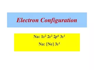
Role of Angle: Andalusite • Natural Mineral • Al2SiO5 • Orthorhombic (Pnnm) • a=7.7942 • b=7.8985 • c=5.559 • 32 atoms/unit cell • Sample Prep • Crushm Disperse on holey carbon film • Random Orientation 2 C.W.Burnham, Z. Krystall. 115, 269-290, 1961
Experimental Multislice Measured and Simulated Precession patterns Bragg’s Law Simulation Precession Off 6.5 mrad 13 mrad 18 mrad 24 mrad 32 mrad
Decay of Forbidden Reflections • Decay with increasing precession angle is exponential • The non-forbidden (002) reflections decays linearly Rate of decay is relatively invariant of the crystal thickness Slightly different from Jean-Paul’s & Paul’s – different case
Precession Projection of Incident beam Quasi-systematic row Precessed On-Zone Systematic Row Forbidden, Allowed by Double Diffraction
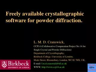
e- e- Evidence: 2g allowed Si [110] Si [112] Rows of reflections arrowed should be absent (Fhkl = 0) Reflections still present along strong systematic rows Known breakdown of Blackman model
+ + + + + + 36 + 24 12 0 mrad + Phase and Averaging For each of the incident condition generate 50 random phase sets {f} and calculate patterns: Single settings at 0, 12, 24 and 36 mrad (along arbitrary tilt direction). At fixed semi-angle (36 mrad) average over range of a as follows: 3 settings at intervals of 0.35º 5 settings at intervals of 0.35º 21 settings at intervals of 1º For each g and thickness compute avg., stdev:
Phase independence when averaged single setting 3 settings, 0.35º interval 5 settings, 0.35º interval 21 settings, 1º interval (approaching precession) Sinkler & Marks, 2009
Why does it work? • If the experimental Patterson Map is similar to the Bragg’s Law Patterson Map, the structure is solvable – Doug Dorset • If the deviations from Bragg’s Law are statistical and “small enough” the structure is solvable – LDM
Why is works - Intensity mapping • Iff Iobs(k1)>Iobs(k2) when Fkin(k1) > Fkin(k2) • Structure should be invertible (symbolic logic, triplets, flipping…)
Summary • PED is • Approximately Invertable • Pseudo Bragg’s Law • Approximately 2-beam, but not great • Properly Explained by Dynamical Theory • PED is not • Pseudo-Kinematical (this is different!) • Fully Understood by Dummies, yet