Download
1 / 18
180 likes | 399 Views
60 GHz WLAN Experimental Investigations. Date: 2008-09-08. Authors:. Abstract. This contribution describes experimental results obtained for 60 GHz WLAN system. 60 GHz WLAN Systems. It is known that propagation channel characteristics are different for 60 GHz than for 2-5 GHz band [1].

E N D
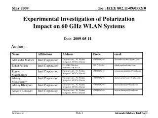
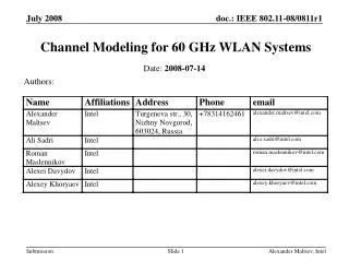
60 GHz WLAN Experimental Investigations Date: 2008-09-08 Authors: Alexander Maltsev, Intel
Abstract • This contribution describes experimental results obtained for 60 GHz WLAN system. Alexander Maltsev, Intel
60 GHz WLAN Systems • It is known that propagation channel characteristics are different for 60 GHz than for 2-5 GHz band [1]. • The consequence of the propagation channel properties is that to be able to achieve WLAN communication range and operate in the NLOS conditions the 60 GHz WLAN systems will require to use steerable directional antennas on both ends of the communication link. This will have major impact on all aspects of the design of such systems including PHY, MAC and others. • The antenna systems will have to use directive transmission principles instead of the diversity principles exploited by multi-element antenna systems of 2-5 GHz WLAN devices. Alexander Maltsev, Intel
60 GHz WLAN System Prototype • The initial prototype of the 60 GHz WLAN system has been developed to investigate the discussed concept of such systems. • The main characteristics of the prototype: • 60 GHz RF frequency with 2 dBm TX power • Horn antennas with 18 dB gain and 17 deg. 3 dB beamwidth • Mechanical steering of antennas using servo motors • 800 MHz baseband channel bandwidth • The automated mechanical steering of TX and RX horn antennas in both azimuth and elevation directions was used to investigate the propagation characteristics and the potential communication links which can be used for such systems. • All combinations of TX and RX antennas positions were tested and the combinations of TX and RX antenna positions which can be used for communications were defined Alexander Maltsev, Intel
60 GHz WLAN System Prototype Baseband Receiver Transmitter Alexander Maltsev, Intel
Scenarios for Experimental Measurements • Two enterprise environments have been considered for initial set of experiments: • Small conference room • Cubicle environment • Both environments are among the most important for application of the WLAN technology Alexander Maltsev, Intel
Conference Room Experiments • Several sets of measurements have been performed in two similar small conference rooms with big table in the middle. • Examples of TX and RX positions are shown in the figure • The TX and RX antennas with servo motors were placed on the tripods at the height of 1 m above the floor which was about 20 cm above the tables (as shown in slide 5). Alexander Maltsev, Intel
Conference Room Measurement Results Example • Example of RX power distribution vs. RX and TX azimuth angles with RX and TX elevation angles equal to 0 deg (i.e. antennas are steered in horizontal plane) 5 3 1 2 4 Alexander Maltsev, Intel
Conference Room Measurement Results Example • RX power distribution for the same configuration vs. TX and RX elevation angles (scanning in the vertical plane) with azimuth angles equal to 0 deg. • Actually the experiments were performed for 4D scanning (RX azimuth and elevation angles and TX azimuth and elevation angles) and the clusters were identified in 4D space Reflection from ceiling LOS Alexander Maltsev, Intel
Conference Room Measurement Results • The measurements results revealed that the positions of TX and RX antennas providing maximum power of the received signal correspond to the LOS and first- and second-order reflections from the walls, floor and ceiling. • For each experiment all the clusters corresponding to LOS, first-order and second-order reflections were identified (when they were not blocked by other objects like table or chairs). • The RMS deviation of the measured TX and RX azimuth and elevation angles from the ones predicted by the geometrical optics (GO) was found to be equal to 10 deg (with taking into account 17 deg 3 dB antenna beamwidth and 10 deg angle measurement step). • The reflection coefficient was from -4 to -18 dB for first-order reflections and from -9 to -21 dB for second-order reflections • The clusters with the most deviation from GO were due to reflections from the specific objects like metal window jalousie or air-conditioning system at the ceiling. Alexander Maltsev, Intel
Cubicle Environment • The preliminary measurements have been performed for the typical cubical environment. The communication between access point sitting near the ceiling and the laptop located inside the cubicle on the table were studied. Cubicle wall blocking LOS TX RX RX Alexander Maltsev, Intel
Experiment in Cubicle Environment • The block diagram of the performed experiment is shown in the figure below (vertical plane). • In the horizontal plane the LOS direction is perpendicular to the cubicle wall Alexander Maltsev, Intel
Example of Experiment in Cubicle Environment • Obtained RX power distribution vs. RX and TX elevation angles with RX and TX azimuth angles equal to 0 deg • All the clusters shown in the previous slide may be identified in the figure 3 2 1 4 Alexander Maltsev, Intel
Cubicle Environment Measurement Results • The preliminary conclusion is that propagation mechanisms are LOS and reflections as for the conference room environment. Besides transmission (penetration) through cubicle walls can be sufficient for establishing communication links. • The cubicle environment has much more complex geometrical structure than the conference room and much more experiments need to be performed to create reliable channel model for this environment. Alexander Maltsev, Intel
Conclusions on Experimental Results • The experimental results obtained with the developed prototype confirmed that the main propagation mechanisms for the 60 GHz WLAN systems channel are LOS, first- and second-order reflections and in some cases transmission. • Using the obtained experimental results it may be predicted that the 60 GHz WLAN systems will need to use steerable directional antennas at both the TX and RX ends to be able to operate at the WLAN ranges and under NLOS conditions • The dedicated channel models have to be developed by the VHT group to be able to take into account all the above mentioned factors. Alexander Maltsev, Intel
VTH60 and IEEE 802.15.3c Channel Models • IEEE 802.15.3c channel models [2] do not address the WLAN scenarios similar to the scenarios presented above. • For example, the beamforming is supported only in the RX azimuth direction which is evidently not sufficient for the 60 GHz WLAN NLOS environments. • New dedicated channel models for 60 GHz WLAN systems have to be developed by the VHT60 task group that should address all the aspects of design of such systems like provision of full support of steerable directional antennas. Alexander Maltsev, Intel
Conclusions • Preliminary experimental investigations have been performed for the conference room and cubicle environments. • The obtained results show that the signal propagation is in good accordance with geometrical optics laws and that 60 GHz WLAN communication systems will have to use steerable directional antennas at both TX and RX links to operate at NLOS conditions. • In our opinion the currently available amount of information about the 60 GHz signal propagation for WLAN scenarios is not sufficient to make an informed decision about the applicability of some specific PHY and MAC technologies like IEEE 802.15.3c to 60 GHz WLAN systems. Much more experimental work will have to be performed by the 802.11 VHT task group. Alexander Maltsev, Intel
References • A. Maltsev et al “Channel Modeling for 60 GHz WLAN Systems” IEEE doc.: 802.11-08/0811r1 • Su-Khiong Yong “TG3c Channel Modeling Sub-committee Final Report” IEEE doc.: 15-07-0584-01-003c • IEEE P802.15.3c/DF3 Part 15.3: Wireless Medium Access Control (MAC) and Physical Layer (PHY) Specifications for High Rate Wireless Personal Area Networks (WPANs): Amendment 2: Millimeter-wave based Alternative Physical Layer Extension Alexander Maltsev, Intel