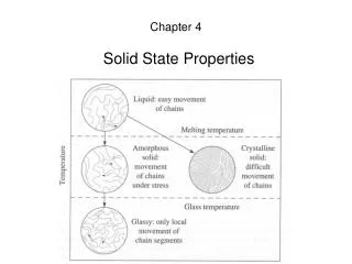
Solid State Electronics
Solid State Electronics. IC Fabrication Technology Ronan Farrell. Recommended Book: Streetman, Chapter 9 Solid State Electronic Devices. Solid State Electronics. The steps involved in making an IC Take a clean ingot of lightly doped silicon

Solid State Electronics
E N D
Presentation Transcript
Solid State Electronics IC Fabrication Technology Ronan Farrell Recommended Book: Streetman, Chapter 9 Solid State Electronic Devices Fabrication Technology
Solid State Electronics The steps involved in making an IC • Take a clean ingot of lightly doped silicon • Use photolithography and photo-resists to define a shape • Remove unexposed photoresist, bake. • Use Ion Implantation or diffusion to add any needed doping • Grow any SiO2 needed. • Create any polysilicon gates needed. • Add any high doping regions needed, p++, n++, • Remove all photoresists • Anneal • Deposit metal. • Planarize • Repeat for each level of metal. Fabrication Technology
IC Fabrication - Wafers and Ingots All silicon processes use wafers. Wafers are thin slices of a cylinder of lightly doped, extremely pure, silicon. These cylinders are called ingots. The doping is normally on the order of 1013 dopants/cm3. Ingots are grown from a vat of pure molten silicon and with a single starter crystal, the ingot is rotated and pulled slowly in order to get a ingot comprising entirely of a single crystal. The speed of rotation and of pull determines the diamater of the ingot . Bigger is better, 12” is the current best commercially usable size. Fabrication Technology
IC Fabrication - Wafers and Ingots Ingot and wafer manufacture is a highly specialised task and is generally not done by the fabrication companies. There is never enough silicon ingots to satisfy current demands. Fabrication Technology
IC Fabrication - Photolithography The basic principle of photolithography is that using a chemical, called a photo-resist, can have it’s chemical properties changed by exposure to light, commonly UV, but now tending to even smaller wavelengths. This change in the photo-resist makes it either • resistant to removal by an organic solvent. (negative photoresist) • Susceptible to removal by a solvent. Which part of the wafer is exposed to the light is controlled by shining the light through a coloured mask, protecting some some areas, exposing others. Fabrication Technology
IC Fabrication - Photolithography Fabrication Technology
IC Fabrication - Photolithography Before applying the photoresist a layer of SiO2 is grown (details later) to act as a barrier and to protect the wafer beneath. The photoresist is applied as a liquid onto the spinning disk and the centrifical forces spreads it out evenly. After exposure to the light, the photoresist is washed. Assuming negative photoresists, the photoresist exposed to the light remains after being washed by the solvent. The wafer is then baked, hardening the photoresist. Fabrication Technology
IC Fabrication - Photolithography Acid (normally HF) is applied, as before using the spinning technique, which eats the SiO2 to reveal holes in the photoresist leading to the wafer The photoresist then acts as a barrier, a protector, to anything that we try to apply to the silicon. This allows us to treat the entire wafer as one, knowing that after using the photoresist only the areas we want to be affect will be. Every time we want to make a modification to the silicon structure, add P type doping, add N type, add metal, we perform an additional cycle of • apply photoresist • expose to light source • remove photoresist • bake Fabrication Technology
Dopant Implantation After baking the photoresist, there are now holes in the protective layer through which we can access the silicon beneath. One of the most important tasks is to add dopant. This lets us change the lightly doped bulk material (say P type) to N and maybe later back to P. There are two techniques for doing this. The more common but rapidly declining approach is diffusion implantation, the newer approach is ion implantation. Both operate on the principle of adding dopant ions, boron, phosphorous, arsenic, to the bulk silicon. NOTE: semiconductor manufacture uses some really nasty chemicals. Fabrication Technology
Diffusion Implantation In diffusion implantation, the wafer is placed inside a heated furnace, heating the wafer to approximately 1000 degC. A gas containing the dopant is passed over the heated wafer. At these temperatures, the dopants can diffuse into the silicon as the heat has weakened the crystalline bonds of the silicon. The doping is greatest at the surface and then diffuses into the material with a gaussian distribution. However the dopant will not only diffuse down into the material but will also diffuse sideways, under our protected regions. This is the great weakness of this approach, sharp changes in doping are hard to obtain, so device sizes have to be big enough to accept that the edges may be blurred a little. Fabrication Technology
Ion Implantation Fabrication Technology
Ion Implantation The other technique involves bombarding the surface of the wafer with dopant ions. In the photoresist+SiO2 covered regions, the ions are absorbed by these materials. In the unprotected regions, the high energy ions enter the wafer. The depth of doping and the quantity of doping can be independently controlled, the depth is based primarily on the energy of the ions, how fast they impact, and the quantity by the number of ions/second you send at the wafer. The other great benefit of this approach is that sideways diffusion of the dopants is a lot smaller than with the diffusion approach. Two problems arise with this • lattice damage due to high energy impacts • very narrow doping profile. Fabrication Technology
Ion Implantation Lattice Damage The high energy impacts of the dopant ions can distort and damage the crystalline lattice structure of the silicon. These dopants are coming in at high speed, hit a silicon atom, move it and takes it’s place. Hence the damage. In this shape, it’s not very useful as a semiconductor. Narrow Doping Profile Unless you vary the kinetic energy of the dopants, which you won’t, most of the dopants will penetrate on average the same distance into the silicon, resulting in a highly doped band under the surface of the wafer. The solution to both of these problems is annealing. Fabrication Technology
Annealing Annealing is the process of heating the silicon up to where the lattice structure begins to weaken, about 1000degC. It’s left there for 15-30 minutes. The heat vibrates the atoms and if done correctly, the bonds in the crystalline structure realign themselves in their most stable form. This corrects any lattice damage and encourages the diffusion of any bands of concentrated dopants. This is a benefit when allowed happen for a little while but if left too long in this heated stage, then all your P and N type dopants will continue to diffuse until you lose all structure. Annealing is only done after ALL processing steps have been completed. Repeated annealing would encourage the diffusion of all the earlier steps. Fabrication Technology
Growing SiO2 SiO2, silicon oxide, is very important in the IC industry as it is an excellent insulator. Being able to grow silicon oxide is very important. It is worth noting that oxidising a P type region, an N-type region, or an intrinsic region will all produce an SiO2 regions. It doesn’t matter to an insulator if it has some P or N type impurities. So SiO2 can always be grown. There are two techniques for growing a layer of silicon oxide, and the choice normally depends on what you need. • Wet Etching: for rapid, deep but less dense SiO2 concentrations. • Dry Etching: for slower, shallow thin layers of higher quality SiO2 layers. Fabrication Technology
Growing SiO2 Wet Etching: In wet-etching high temperature steam (900 degC) is passed over the wafer. The water vapour diffuses into the silicon and the following reaction occurs. Dry Etching: In dry-etching high temperature (1100 degC) oxygen is passed over the wafer and directly oxidises the silicon, forming the oxide. This is a slower process but is good for forming thin layers of high quality oxide. Fabrication Technology
Growing SiO2 Oxidation makes the silicon oxide grow in volume compared to the pure silicon, a factor of 2.2, so in cross-sectional views, you’ll see a bulge due to the SiO2. Fabrication Technology
Depositing Metal Metal needs to be very tightly controlled on a chip. If it entered the dopant mix, it would severely damage any attempted doping. Even trace amounts, especially of copper, would be enough. However we also need to connect terminals of devices together with metal. Traditional Aluminium has been used as it has less tendency to diffuse into the silicon over the operational lifetime of the device. It is also important to pick a metal with as little resistance as possible as wires are very narrow but can be very long, resulting in a very large resistance. Copper technology Fabrication Technology
Depositing Metal One piece of terminology used in the semiconductor industry is squares. Consider a piece of wire, of fixed depth, d L W The depth of a wire in a semiconductor process is fixed, so the equation for resistance is where the ratio of L/W is called the number of squares in the wire. Resistivity is given as R= (resitivity)*squares, taking the depth into account. Fabrication Technology
Depositing Metal To visualise what squares mean, consider the following wire. Assuming it’s resistivity is This approach makes it very easy to see which wires are high and low resistance. Fabrication Technology
Depositing Metal Metal is normally deposited by evaporation. The metal is evaporated and settles onto the exposed areas of the wafer. The evaporation is highly controlled and done local to the region in which you want to deposit the metal. The evaporation can be done by electron beam bombarding of a metal source or by ion bombarding. Fabrication Technology
Multi-Level Chips As chip technology has gotten better more and more layers of metal can be deposited. These layers are seperated by SiO2 to ensure that they don’t short-circuit. Metal tracks on different layers connect to each other by vias which are made in the same way as before, you make a mask, leave a hole in the oxide and photoresist, fill it with metal, and then proceed with your next layer of metal. It can look quite spectacular when acid is used to etch away all the oxide, just leaving the metal tracks behind. Fabrication Technology
Multi-Level Chips The metal here is just coloured to indicate the different levels. Fabrication Technology
Planarization Before a mask can be applied, the surface needs to be very smooth, exceptionally smooth so as not to create shadows or to distort the projected image from the mask. This process is called planarization and normally involves a combination of chemical etching and mechanical grinding. We are grinding something so smooth that the greatest bump should be no more than the minimum device geometry. So for a 0.1um process, the bumps are to be smaller than 0.1um. This is a ratio that says if each bump was 1meter, then 1 meter would be about the diameter of the Earth. Fabrication Technology
Bonding The last process that a chip undergoes is bonding. Right at the top of the chip big metal pads are added. To these, thin gold metal wires are soldered and are brought to the pins of a plastic/ceramic package that will hold the chip. These let us use the silicon inside. On chips with lots of pins, bonding becomes a nightmare, requiring complicating pin geometries and complex packages, for example look at the intel processors. Fabrication Technology