Axial Force Member Design
190 likes | 900 Views
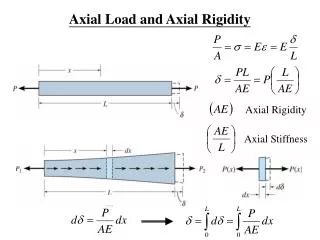
Axial Force Member Design. CE A433 – Spring 2008 T. Bart Quimby, P.E., Ph.D. University of Alaska Anchorage Civil Engineering. Tension Members. Members subject to axial tension include truss elements, diaphragm chords, and drag struts. The basic Design Inequality is: ASD: f t < F’ t

Axial Force Member Design
E N D
Presentation Transcript
Axial Force Member Design CE A433 – Spring 2008 T. Bart Quimby, P.E., Ph.D. University of Alaska Anchorage Civil Engineering
Tension Members • Members subject to axial tension include truss elements, diaphragm chords, and drag struts. • The basic Design Inequality is: ASD: ft< F’t Ta/An< Ft CDCMCF LRFD: Tu<fT’n Tu<f KFFt lCMCFAn
An: Net Area • Net Area accounts for loss of area due to holes and other cuts in the member. • Net Area is the gross area less the area of any grain that is cut. • There is no account for stagger.
Compression Members • Members subject to axial compression include columns, studs, truss elements, diaphragm chords, and drag struts. • The basic Design Inequality is: ASD: fc< F’c Pa/A< Fc CDCMCFCP LRFD: Pu < fP’n Pu < f KFFt lCMCFCP A
A: Area • In Buckling Region • A = Gross Area, Ag • In Non-Buckling Regions (i.e. near ends in most cases) • A = Net Area, An
CP: Column Stability Factor • Applies only to compressive stress, Fc • Applies to both Sawn Lumber and Glulams • Found in NDS 3.7.1 • This factor accounts for instability in laterally unsupported columns (i.e. column buckling) • Different in each principle direction
More CP • See NDS Equation 3.7-1 • Column buckling is a function of the laterally unbraced (buckling) length, le, and cross section properties (Moment of Inertia, Ie, and Area, A) and is different in each principle cross section direction. • First check the slenderness ratio • le/d must not exceed 50 • Then compute CP • Note that CP is a function of the member size! • This means that you must know the member size before computing this factor • When designing, this dependency leads to iterative computations
Laterally Unbraced Length, lu • This is the distance between locations of lateral support in the plane of buckling • Most members have two principle directions and lu is frequently different in each direction. Weak Axis Buckling Strong Axis Buckling
le: Effective Length • Effective length is a function of the laterally unbraced length and the end conditions. • Most timber connections are considered to be pinned. Effective Length Coefficients From AISC Steel Construction Manual
Slenderness • NDS 3.7.1.4 • The slenderness ratio le/d must not exceed 50 • luy1/d1, luy2/d1 • lux1/d2
Computing CP • NDS Equation 3.7-1 • Accounts for buckling and material strengths Material Strength Euler Strength
Combined Bending & Axial Force NDS 3.9
Combined Axial Force and Bending • Both axial force and bending create normal stresses on a cross section. stotal, x,y = saxial + sbending-x + sbending-y sx,y = P/A + Mxy/Ix + Myx/Iy • The result is a planar equation across the section.
Allowable Composite Stress • Note that each stress component has a DIFFERENT allowable stress, so the limiting value of the combined stress needs to be a composite of the individual allowable stresses. saxial<saxial,allowablesbending-x<sbending-x,allowablesbending-y<sbending-y,allowable scombined<scombined,allowable
Combining Allowable Stress • These can be rewritten as the following ratios: saxial / saxial,allowable< 1.00sbending-x /sbending-x,allowable < 1.00sbending-y / sbending-y,allowable < 1.00 • In each case, the ratio goes to 1.0 as the normal stress approaches it’s allowable
Interaction Equation • Instead of finding a composite allowable stress, we can combine the stress ratios saxial / sa,allow + sbx /sbx,allow + sby / sby,allow < 1.00 • Most combined stress and combined force equations used in structural engineering use this form.
Second Order Effects • Secondary moments are created with axial force is applied to an already bent member. • See text in A Beginner’s Guide to the Steel Construction Manual, section 10.3 for more explanation about second order effects. • Second order effects are ignored in combined tension and bending • Second order effects can be very significant in combined compression and bending
Bending & Axial Tension • NDS 3.9.1 • Both interaction equations must be satisfied.
Bending & Axial Compression • NDS 3.9.2 • Moments are “magnified” by the factors