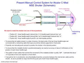
Download
1 / 8
80 likes | 260 Views
TORIC and AORSA are being used to design flow drive experiments on Alcator C-Mod. Work by Myra, Jaeger et al. [PRL, 2003] demonstrated significant shear flow generation is possible in fast wave to ion cyclotron wave (ICW) mode conversion experiments on C-Mod [Melby et al., PRL, 2003]:

E N D
TORIC and AORSA are being used to design flow drive experiments on Alcator C-Mod • Work by Myra, Jaeger et al. [PRL, 2003] demonstrated significant shear flow generation is possible in fast wave to ion cyclotron wave (ICW) mode conversion experiments on C-Mod [Melby et al., PRL, 2003]: • Mechanism relies on mode converted ICW damping at ion resonance as wave propagates back toward the tokamak LFS. • TORIC and AORSA are being used to identify C-Mod scenarios (multi-ion species) where cyclotron absorption is maximum and electron damping of ICW is minimized. • Code comparisons [J.C. Wright et al., PoP, 2004] are a critical feature of these studies to cross-check high resolution TORIC simulations against integral conductivity operator of AORSA.
Field solvers employing different conductivity models give very similar results TORIC at 240Nr x 255 Nm J. Wright, PSFC, PoP, 2004 ICW IBW FW AORSA at 230Nx x 230 Ny E.F. Jaeger, PRL, 2003
RF SciDAC Project is Providing Critical Input to ITPA For ICRF Code Benchmark Activity • ICRF Simulations of 2WT Heating in the ITER Device Are Being Performed using AORSA and TORIC: • Calculations use ELMY H-Mode Parameters (ITER Scenario 2). • Include energetic fusion alpha particle population.
Initial Comparisons Between AORSA and TORIC are Favorable • Power balance - TORIC P(2T) = 50 % P(ELD) = 35% P(D) = 1.8% P(alpha) = 14 % Bi-Maxellian for f(v) Teff=1.6 MeV • Power balance – AORSA2D P(2T) = 45 % P(ELD) = 38% P(D) = -0.5% P(alpha) = 17 % Slowing down distribution for f(v) Calculations using exact f(v) from CQL3D are in progress
TORIC Results for ICRF Absorption (Nm=127, NR=480)Don and Fred – Below Please Insert a Comparison Figure From AORSA ! Injected fast wave electric fields exhibit strong focusing
Antenna coupling for impedance calculations under way using TOPICA3 + 2D Wave Solver - TORIC– to be completed in 4 weeks • Review the relationship between H and E on the LFS and to develop the final form of the reaction integrals in the spectral domain -Torino, done. • Find the best way to approximate the aperture and transform to the spectral domain -Torino, done. • Code a subroutine implementing the aperture transform in 2)-Torino to do. • Code changes to TORIC solver and output routines to do impedance calculation for individual nf M{n} and mq b{m}– MIT to do. • Combine with per mode loading from TOPICA to get total loading and fields consistent with that loading in postprocessing step– MIT/Torino to do. Toric stiffness matrix, M, is fctn of nf, boundary vector; b is a fctn of antenna mode pair. Solution, x, is one column in impedance matrix, Ym,m', which is closely related to M-1
TOPICA3 was recently coupled to the 1D Wave Code FELICE and used to simulate loading in the Alcator C-Mod “E” Antenna (R. Maggiora et al., APS, 2005) Computed Loading Computations and Code Implementation on the MIT Beowulf Cluster – Using the measured density profiles in the C-Mod SOL. Plasma shot Measured Loading
Free boundary MHD simulations and ideal stability analysis with self-consistent current profile control • RF simulator with driven RF current electron response will soon be available [CQL3D+TORIC and CQL3D + AORSA]: • Current density source terms due to LHCD, FWCD, or MCCD. • Plan to couple the driven current source term to a free boundary MHD solver and iterate [ACCOME code - Bonoli, Ramos, Kessel et al., PPCF, 1997]: • Resulting MHD equilibrium and current density source terms are then consistent with each other. • MHD equilibrium can then be tested for ideal stability (ballooning and low-n external kink modes) by coupling to a stability package [PEST-II]. • As a first step, the ACCOME code has been successfully implemented and tested on the MIT Beowulf cluster.