Download

1 / 26
370 likes | 686 Views
The Von Neumann Model. The whole model. Four basic components: Memory A processing Unit Input Output Control. MDR = Memory Data Register MAR = Memory Address Register PC = Program Counter IR = Instruction Register ALU = Arithmetic and Logic Unit LED = Light Emitting Diode.

E N D
The whole model • Four basic components: • Memory • A processing Unit • Input • Output • Control MDR = Memory Data Register MAR = Memory Address Register PC = Program Counter IR = Instruction Register ALU = Arithmetic and Logic Unit LED = Light Emitting Diode
Something about memory • Memory in its most general sense refers to places to put things for later retrieval. • Some special memory for temporary storage (registers) is located on the processor chip. • Access to this memory is extremely fast, but it is very expensive and in very small supply (16, 32, that sort of number). • Mostly, when we talk about memory, we mean RAM -- Random Access Memory
RAM • An array of bits • Addressability refers to how many bits are associated with each address provided. • N bit address can access 2N locations • In our 4 x 3 example, there were four addresses, each of which specified a set of three bits • Power required to store the value • Gated D-latch type of circuit • Has to be loaded after the computer is powered up
RAM continued If the computers of today contain 2 to the 28th by 8 bits, then how does the 256 megabyte memory come into play? What exactly is 256? • Amount of RAM is now measured in Gigabytes • Giga means billions • Kilo (K) is actually 1024 • Mega (M) is actually 1,048,576 • Giga (G) is actually 1,073,741,824 • byte means 8 bits (almost always) • How big an address would be required to access each byte in an 80 GB memory? • Word size is the number of bits accessed at one time in a particular machine’s architecture
More RAM • To access the content of a memory location, specify the location (its address) • Location and content are two distinct, very important concepts. • We will see the distinction clearly when we study the C language. (C allows us to manipulate the address, as well as the content) • Memory can be read from or written to. • Reading is non destructive -- what was there before remains • Writing is destructive -- what was there before is replaced by the new information.
Reading and Writing RAM • MAR contains the address to be used (the values on the A lines in our map of a small memory) • MDR contains the data to be written (if writing) or will receive the value read (if reading) • These are two registers (located on the processor chip) that are dedicated to these specific purposes.
Processing Unit • The location of all the circuitry related to manipulating the bits for achieving some purpose • The Arithmetic and Logic Unit • performs arithmetic and logical operations on data stored in registers, usually. (It would be very inefficient to have these circuits try to access RAM directly) • Registers • local storage for data in immediate use
Control • We have memory to store instructions and data, and the processing unit to carry out operations. • The control unit determines what happens next and keeps the processing unit supplied with the next instruction. • Good question asked: How are these instructions which allow the computer to operate defined. Meaning were do they originate from (RAM, bios, etc.) and how do they function in the processor.
From the beginning… R0 R1 R2 … IR PC MAR The bare machine without power. Nothing is happening. MDR The control unit controls the rest of the computer’s functions. How does the control unit figure out what it has to do first and where it looks for the components it needs to run. Memory - empty
To get started Something else is needed. ROM stores the instructions needed to get started. When power is available, the circuitry in the computer loads the contents of ROM into a predetermined location in memory. R0 R1 R2 … IR PC MAR MDR ROM Memory -
First steps R0 R1 R2 … IR PC MAR Now, these few instructions control the computer. They have one purpose – to load the operating system core into memory and turn over control of the computer to the operating system. MDR 00..0 00010100… 00..1 00..2 00..3 Etc…. Memory -
Under control of the OS R0 R1 R2 … IR Now the OS is in control. The user commands to the operating system asks for the appropriate application program to be loaded. In turn, the application program calls for its data as needed. PC MAR MDR Memory - OS loaded
What operations? • That’s what makes machines different • The list of things that a given machine can do is called its Instruction Set • The Instruction Set Architecture (ISA) is the description of what a given machine can do, including the instructions it can execute and the amount of local memory it has available to work with. • An instruction is a combination of bits with a specific meaning. • Think of an instruction as a set of switch settings
Instructions • Can you wash your clothes in your microwave oven? • Of course not, because that is not in the ISA of a microwave. • Are all microwave ovens alike? • No. They vary in power and in conveniences such as rotating trays. • Some microwave ovens have an “instruction” (a setting) for baking a potato. Others do not have that instruction, but can do the same thing if you give it the right steps to follow.
CPU • The central processing unit of the computer is where the work gets done. • The instruction set of a particular computer consists of the recognized instructions -- ADD, AND, NOT, OR, Subtract, Multiply, Divide, Move, Compare, etc. • The list varies from one machine to another. • All general purpose computers are equivalent. Given enough memory and enough time they can do the same things. (They are all Turing machines.)
Input and Output • A computer is not very useful if we are unable to give it commands and see what it has done • Input is a way of getting instructions and data into the computer. • Mouse, Keyboard, sensors, scanners, • Output is a way of getting results out of the computer • Monitor, printer, plotter, etc. • Some devices are used for both input and output • CD-RWs, various disks, network connections, etc.
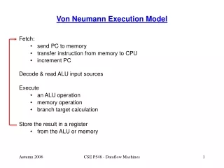
The instruction cycle • Basic version: fetch and execute • More detailed version: • fetch, decode, evaluate address, fetch operands, execute, store result • Underlying theme: • Instructions and data are stored in RAM until needed. • To execute an instruction, the CPU has to find the instruction, move it into the IR, find the data, move it into registers, carry out the instruction and store the result back in memory
The LC-2 In Fig 4.3, what are the 3 arrows marked DR, SR1, and SR2 that go out of the control logic box? Where do they output to? DR = Destination register SR = Source Register Any others? the LC-2 drawing on pg 80 confuses me, because the PC seems not to connect to the MAR or main memory or anything, and i don’t know what the purpose of those two big arrows pointing to the left are.
Finding the instruction and data • The MAR contains the address of the instruction or the data to be fetched. How the MAR gets its value is an important part of how the computer works. • In the normal cycle, the PC is incremented to point to the next physical location. (Not all computers require that the PC contents be moved to the MAR. The PC can serve as an MAR for fetching instructions.) • To fetch data, the MAR must be loaded explicitly from information provided in the instruction.
Example instructions • In each type of computer, there is a specific format for each type of instruction. (Refer to the IBM 360/370 ISA distributed earlier.) • Each bit position has meaning • A bit is part of the operation to be performed or part of the specification of the location of data or the location where the result will be stored. • There are a number of formats for specifying the location of data. More about that soon.
ADD in the LC-2 • The LC-2 ADD instruction • Bit pattern 0001 means ADD • The source and destination addresses are registers • Bit positions [5:3] are not used • What does instruction • 0001010101000111 mean? 0 15 Result Source 1 Source 2 Op Code How do you know that something is in an ADD instruction format and not an LDR instruction format? Does it have to be labeled? And how would you do an instruction format?
The cycle How do you know that something is in an ADD instruction format and not an LDR instruction format? Does it have to be labeled? And how would you do an instruction format? This is why we have several steps to the fetch execute cycle. After fetching the instruction, we then decode it. Once we know which operation we have, we know what format the addresses will be in. Then we can evaluate the addresses and then we can fetch the operands. Only then can we execute the instruction and store the results.
Other formats The LDR example 15 0 0 0 1 1 0 0 1 0 0 1 1 0 1 1 1 0 DR LDR Base register + offset amount This is just a sample. We will see other addressing formats in the next chapter.
Changing the flow • JMPR • The JMP is a Jump instruction and will specify exactly where the next instruction is to come from. • The R at the end says that the addressing format used is base + displacement • The address obtained will be written into the PC to control where the next fetch cycle will go to find an instruction.
The clock • As we saw with the simulator, a clock in a computer is just a pulse generator. It cycles at regular intervals and controls the events occurring. When the clock goes faster, everything in the machine goes faster. If the clock goes too fast, the operations will not be finished and the state of the machine will be confused. If the clock goes too slow, the machine will run slower than it needs to.