Download
1 / 22
220 likes | 370 Views
Cross-layer Visibility as a Service. Ramana Rao Kompella Albert Greenberg, Jennifer Rexford Alex C. Snoeren, Jennifer Yates. IP. Layering in the current Internet. OVERLAYS. MPLS. Ethernet. Optics. Fiber-spans. Fiber. Layering is a mixed blessing.

E N D
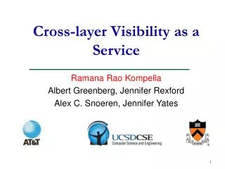
Cross-layer Visibility as a Service Ramana Rao Kompella Albert Greenberg, Jennifer Rexford Alex C. Snoeren, Jennifer Yates
IP Layering in the current Internet OVERLAYS MPLS Ethernet Optics Fiber-spans Fiber
Layering is a mixed blessing • Layering allows us to contain complexity • Each layer evolves independently without affecting any other layer • Allows us to focus on one layer at a time • There are associated challenges too… • Routine operational tasks need associations across layers • Example: mapping an IP link to optical circuit, overlay link to an IP path • Lack of accurate cross-layer associations can affect the reliability of the network
Intended planned maintenance Planned maintenance on optics Seattle Boston Denver New York Chicago San Francisco St Louis Los Angeles Orlando Dallas
Intended planned maintenance • Optical component is on circuit id A • Lookup database to map circuit id A to IP link • Due to mis-association, incorrectly maps it to LA to Dallas • Increase OSPF weight on LA to Dallas link • Disconnect component • Causes failure LA to San Francisco link is congested Traffic from LA to Dallas is rerouted via Denver Planned maintenance can induce faults if accurate associations are not maintained Denver X San Francisco Los Angeles Dallas High OSPF weight
Sprint Internet Level 3 New York Customer in NJ INTER-CARRIER DIVERSITY Customer Fault Tolerance Internet New York Shared optical element Customer diversity information requires accurate cross-layer associations, sometimes across domains Customer in NJ INTRA-CARRIER DIVERSITY Philadelphia Going through same conduit or Holland tunnel ?
Fault diagnosis Because of a bug, IP forwarding path changed, but MPLS did not ! Seattle Boston Denver New York Diagnosing faults requires accurate cross-layer associations Chicago San Francisco X St Louis Los Angeles Orlando Dallas MPLS circuit between LA and New York What happened ?!!
Why is it hard ? • Can’t the operators maintain associations in a centralized fashion ? • Maintain database as links are provisioned • Update as and when interfaces are re-homed • Hard due to flux in topology • Churn because of dynamic topology changes • Human errors during re-homing interfaces • Operational realities – separation of concerns
How it is done today ? • A combination of non-standard databases • Human-generated inventory data • Measurement data obtained from probes • Configuration state from network elements • Policies implemented in network elements • Higher complexity and overhead • No compatibility across ASes • Difficult to evolve a network • Difficult to integrate two networks after acquisition • Difficult to incorporate third-party tools
Why not concentrate on restoration? • Advantages of lower-layer restoration • Hides lower-layer failures from impacting upper layers • Obviates to some extent need for cross-layer visibility • Cross-layer visibility still important • Lower-layer restoration more expensive than IP restoration • Subtle performance changes (e.g., RTT) need diagnosis
Why not fatten the interfaces ? • Fattening interfaces to make layers aware of the entire topologies above and below • Layers discover and propagate mappings automatically • Management system can query the network to obtain mappings • Fattening results in high complexity • Interoperability is a big challenge – long design and test cycles • Wider interfaces impact security
IP Architecture for cross-layer visibility BOW-TIE OVERLAYS Backbone planning MPLS Cross-layer Policy Server Customer diversity Ping Trace-route Backbone maintenance Ethernet Optics Fault diagnosis DB Fiberspans Fiber MANAGEMENT APPLICATIONS IP HOUR-GLASS
OVERLAYS OVERLAYS MPLS MPLS IP IP Optics Optics FIBER, FIBERSPAN FIBER, FIBERSPAN Standardize what goes in ! Standardize what goes in (e.g. IP topologies) AS1 Facilitates interaction between ISP policy servers AS2
Advantages of the bow-tie • Topology, routing information and other associations can be queried for maintenance, diversity, and fault diagnosis • Cooperation across ASes to present better visibility across domains • Policies easily enforced through the server • Lower overhead on network elements • Caching of common queries possible • Historical questions can be answered
Evolution path to improve accuracy • A lot of room for improvement • Architecture accommodates evolution so that accuracy can be improved over time • Evolution path for individual layers • Fiber & Fiber-spans • Optical components • IP links • MPLS and overlay paths
Fiber & Fiberspans FIBER • Automated mechanisms [sebos02] • Inject labels through fibers or use RFID • GPS to determine the location of fibers • Transmit this information to the DB • More coverage results in better accuracy but expensive OPTICAL TAPS / RFID GPS DB FIBER
Optical components • Manual mechanisms • Basic consistency checks • Automatic correlation mechanisms such as [kompella05nsdi] to output errors • Automatic mechanisms • Neighbor discovery for active optical devices • Configuration state from “intelligent” optical networks (that support dynamic restoration)
Optical components Configuration state during restoration Neighbor discovery through periodic broadcasts at optical layer Intelligent Optical Network ROUTER B ROUTER A DB
Other layers • IP layer • Periodically obtain configuration information to construct topology • Automatically collect up/down messages to provide up-to-date view • MPLS and overlay paths • Static paths obtained from configuration • Dynamic paths obtained by monitoring signaling messages
Summary • Accurate associations critical to many operational tasks • A bow-tie architecture for cross-layer visibility • Provides the cross-layer associations as a service to various applications • Allows better cooperation among ASes through standardizing what goes into the database • Policy controlled export of these associations • Lower overhead on network elements • Allows for innovation while containing complexity
Future research directions • Design automated mechanisms at each layer to improve cross-layer visibility • What frequency should information be obtained? • How do we resolve conflicts (minimal edits) in the database? • Identify higher-level models that we need to standardize • Devise incentives for cooperation among ASes • Define a language to specify policies