Download
1 / 41
800 likes | 1.64k Views
Condensate Recovery. Dr. Sanjay Vashishtha Assistant Professor, CREED BITS Pilani. Steam and condensate. Calculating the amount of flash steam from condensate.

E N D
Condensate Recovery Dr. Sanjay Vashishtha Assistant Professor, CREED BITS Pilani
Calculating the amount of flash steam from condensate • Hot condensate at 7 bar g has a heat content of about 721 kJ/kg. When it is released to atmospheric pressure (0 bar g), each kilogram of water can only retain about 419 kJ of heat. • The excess energy in each kilogram of the condensate is therefore 721 – 419 = 302 kJ. • The enthalpy of evaporation at atmospheric pressure, 2258 kJ/kg. • Flash steam evaporated: 302/2258 = 13.4%
Condensate return A typical steam and condensate circuit
Why return condensate and reuse it? • Reduced water charges. • Reduced effluent charges. • Reduced fuel costs • More steam can be produced • Reduced boiler blowdown • Reduced chemical treatment
Layout of Condensate Return Lines Condensate pipework layout depends on: • the application pressure, the steam trap characteristics • the position of the condensate return main relative to the plant • the pressure in the condensate return main. Condensate must not be allowed to accumulate in the plant, Condensate must not be allowed to accumulate in the steam main.
A steam main trap set discharging condensate into a common return line
A 30 kW air heater is to be fitted with a DN15 thermostatic steam trap, which releases condensate at 13°C below saturation temperature. The normal working pressure is 3 bar g, the ambient temperature is 15°C, and the heat loss from the drain line to the environment is estimated to be 20 W/m2 °C. Determine the minimum required length of 15 mm drain line to the thermostatic trap.
Precautions • Keep drain lines short Keep drain lines short
Trap discharge lines pass condensate, flash and incondensibles
Balanced pressure thermostatic trap with cooling leg into a flooded line
Discharge from steam traps on temperature controlled equipment into flooded lines
Sizing of all condensate lines is a function of: • Pressure - The difference in pressure between one end of the pipe and the other. • Quantity - The amount of condensate to be handled. • Condition - Is the condensate predominately liquid or flash steam?
Considerations when sizing the drain line • The condensing rate of the equipment being drained during full-load. • The condensing rate of the equipment at start-up. • For steam mains drainage, the condensate load for each drain trap is typically 1% of the steam capacity of the main based on drain points at 50 m intervals, and with good insulation. • On constant steam pressure processes, sizing the traps on approximately twice the running load at the working pressure will provide sufficient capacity to cope with the start-up load.
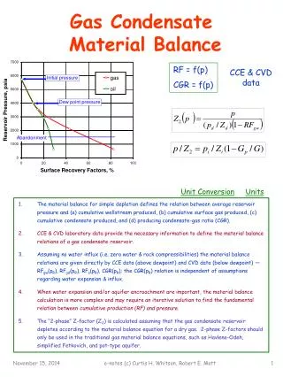
An item of plant uses steam at a constant 4 bar g pressure. A mechanical steam trap is fitted, and condensate at saturation temperature is discharged into a condensate main working at 0.5 bar g.Determine the proportions by mass, and by volume, of water and steam in the condensate main.
Correctly sized trap discharge lines which slope in the direction of flow and are open-ended or vented at a receiver, will be non-flooded and allow flash steam to pass unhindered above the condensate
Non-pumped rising lines should be kept as short as possible and fitted with a non-return valve to stop condensate falling back down to the trap
Example 1: A steam trap passing a full-load of 1000 kg/h at 6 bar g saturated steam pressure through a falling discharge line down to a flash vessel at 1.7 bar g. As the discharge line is non-flooded, the lower figure of 25 mm is selected from the chart
Example 2: A steam trap passing a full-load of 1000 kg/h at 18 bar g saturated steam pressure through a discharge line rising 5 m up to a pressurised condensate return line at 3.5 bar g.Add the 0.5 bar static pressure (5 m head) to the 3.5 bar condensate pressure to give 4 bar g backpressure. As the discharge line is rising and thus flooded, the upper figure of 32 mm is selected from the chart
Example 3: A steam trap passing a full-load of 200 kg/h at 2 bar g saturated steam pressure through a sloping discharge line falling down to a vented condensate receiver at atmospheric pressure (0 bar g).As the line is non-flooded, the lower figure of 20 mm is selected from the chart
Example 4: A pump-trap passing a full-load of 200 kg/h at 4 bar g saturated steam space pressure through a discharge line rising 5 m up to a non-flooded condensate return line at atmospheric pressure.The 5 m static pressure contributes the total backpressure of 0.5 bar g.As the trap discharge line is rising, the upper figure of 25 mm is selected from the chart.
Example 5: Consider a condensate load of 200 kg/h to a receiver and pump. The pump discharge rate for this mechanical type pump is taken as six times the filling rate, hence, the condensate rate taken for this example is 6 x 200 = 1 200 kg/h.Because the condensate will have lost its flash steam content to atmosphere via the receiver vent, the pump will only be pumping liquid condensate. In this instance, it is only necessary to use the top part of the chart
Common return lines It is sometimes necessary to connect several trap discharge lines from separate processes into a common return line. Problems will not occur if the following considerations are met: • The common line is not flooded and slopes in the direction of flow to an open end or a vented receiver or a flash vessel if the conditions allow. • The common line is sized on the cumulative sizes of the branch lines, and the branch lines
Lifting condensate from a steam main Use of a liquid expansion trap