Download
1 / 49
520 likes | 949 Views
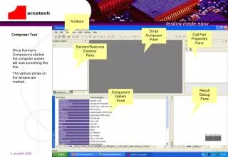
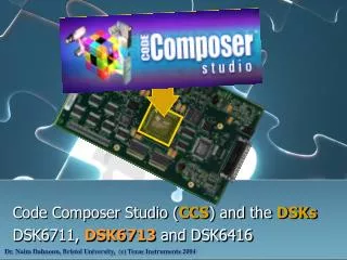
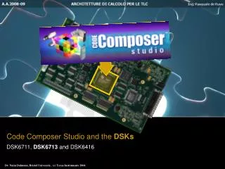
Code Composer Studio and the DSKs DSK6711, DSK6713 and DSK6416. Dr. Naim Dahnoun, Bristol University, (c) Texas Instruments 2004. Learning Objectives. Introduction to C ode C omposer S tudio - CCS Installation and Setup of CCS. Introduction to the DSK-TI.

E N D
Code Composer Studio and the DSKs DSK6711, DSK6713 and DSK6416 Dr. Naim Dahnoun, Bristol University, (c) Texas Instruments 2004
Learning Objectives • Introduction to Code Composer Studio - CCS • Installation and Setup of CCS • Introduction to the DSK-TI • Laboratorio: Implementazione di un filtraggio vocale sul 6713-DSK.
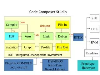
CCSCode Composer Studio The Code Composer Studio (CCS) application provides an Integrated Development Environment (IDE) with an Editor, Compiler, Debugger, Project Manager, Profiler, etc. C/C++ Compiler, Assembly Optimiser and Linker DSP Simulator (for DSKs) Real-Time Operating System - RTOS (DSP/BIOS™) Real-Time Data Exchange (RTDX™) Host - Target Real-time Analysis and Data Visualization
CCSInstallation and Setup (A) Install the CCS Software. (B) Run CCS Setup: • Start CCS setup utility by using the following desktop icon: • Alternatively: • Windows Start Menu -> Programs -> Texas Instruments -> Code Composer Studio 2 (‘C6000) -> Setup Code Composer Studio. • Run cc_setup.exe located in: c:\ti\cc\bin\
CCS Setup • You should now see a screen similar to this: Note: If you don’t see the Import Configuration dialog box you should open it from the menu using: File:Import.
CCS Setup • You can clear the previous configuration by selecting the configuration you wish to clear and clicking the clear button. • Next select a new configuration that you would like to add: • Select the C6x11DSK - Port x - y Mode. • The port number, x, and port mode, y, depend on your PC setup.
CCS Setup • If you do not know your configuration then you can select it automatically using the “Configure C6x11 DSK” Utility.
CCS Setup • Finally Save and Quit the import configuration dialog box.
Using CCS • Start CCS by either: • Using the desktop icon: • Start -> Programs -> Texas Instruments -> Code Composer Studio 2 -> Code Composer Studio. • Run cc_app.exe in c:\ti\cc\bin\
Troubleshooting • If the following window appears on your screen then: • Check that the DSK is connected properly and powered up. • Check if the port address and mode is correct (See Slide 6).
+ Introduction to the ‘C6711 DSK • The ‘C6711 DSK provides a powerful, low-cost development environment. • The DSK comes with CCS code development tools (does not include the simulator).
+ DSK6711 Contents • Hardware • 150 MHz‘C6711 DSP • TI 16-bit A/D Converter (‘AD535) • External Memory • 16 MB SDRAM • 128 kB Flash ROM • LED’s • Daughter card expansion • Power Supply & Parallel Port Cable • Software • Code Generation Tools (C Compiler, Assembler & Linker) • Code Composer Debugger (256K program limitation) • Example Programs & S/W Utilities • Power-on Self Test • Flash Utility Program • Board Confidence Test • Host access via DLL • Sample Program(s)
+ Hardware: Overview • The daughter card interface socket provides a method for accessing most of the C6711 DSP for hardware extension. 1.8V Power Supply 16M SDRAM 128K FLASH Daughter Card I/F (EMIF Connector) Parallel Port I/F ‘C6711 DSP TMS320C6711 Power Jack D. Card I/F (Periph Con.) Power LED User DIP switches Three User LEDs Reset 3.3V Power Supply 16-bit codec (A/D & D/A) Emulation JTAG Controller JTAG Header Line Level Input (microphone) Line Level Output (speakers)
+ (A) Parallel port: The PC’s parallel port is connected to the parallel port on the DSK. Parallel Cable External Power Supply HPI PC DSK Power Supply Line-level Output Line-level Input JTAG (B) JTAG: An XDS - JTAG emulator connected to the PC (either internal or external) is connected to the JTAG header on the DSK. PC DSK XDS External Power Supply Power Supply Line-level Output Line-level Input Hardware: DSK Connections
+ Test LED 3 LED 2 LED 1 Description 0 0 0 0 Start state 1 0 0 1 DSP internal SRAM test 2 0 1 0 External SDRAM test 3 0 1 1 DSP McBSP0 loop back test 4 1 0 0 External codec read/write test 5 1 0 1 External codec tone generation test 6 1 1 0 External LED and DSP timer test 7 1 1 1 Unused – available for future test use B L I N K A L L All tests completed successfully Hardware: Power On Self Test (POST) • There are three LEDs to provide the user with feedback from the test procedure. • The Test Program (stored in the FLASH memory, code available on the DSK CD-ROM) runs every time DSK is powered on and reset.
+ CCS Reset • Menu selection:DebugDSP Reset • Resets ‘C6711 DSP • Causes bootload from FLASH which overwrites internal memory TMS320C6711 Absolute Reset On rare occasions you might have to: • Pull power jack • Pull parallel port Apply Power • POST runs Power On Self Test (POST) • Counts 1 - 7 • 4: mic input spkr out • 5: sinewave spkr out • Don’t start CCS until end (all 3 LEDs flash at the end) • If switches are set to 0100, a fast version of POST is run Reset Pushbutton • Don’t push when CCS is running • Does not force FULL system reset • To fully reset board, pull power plug Hardware: Resets
+ TMS320C6711 ‘C6711 DSK 0000_0000 16 MB SDRAM 64 kB Internal – L2 (Program or Data) Program File 128 kB FLASH 0180_0000 On-chip Peripherals 9008_0000 4 byte I/O Port Program File • LED’s • Switches • DSK status • DSK rev# • Daughter Card 8000_0000 CE0 -128 MB External Available viaDaughter Card Connector 9000_0000 CE1 - 128 MB External A000_0000 CE2 - 128 MB External B000_0000 CE3 - 128 MB External FFFF_FFFF Hardware: Memory Maps
+ Description Origin Length Internal RAM (L2) mem 0x00000000 0x00010000 EMIF control regs 0x01800000 0x00000024 Cache configuration reg 0x01840000 0x00000004 L2 base addr & count regs 0x01844000 0x00000020 L1 base addr & count regs 0x01844020 0x00000020 L2 flush & clean regs 0x01845000 0x00000008 CE0 mem attribute regs 0x01848200 0x00000010 CE1 mem attribute regs 0x01848240 0x00000010 CE2 mem attribute regs 0x01848280 0x00000010 CE3 mem attribute regs 0x018482c0 0x00000010 HPI control reg 0x01880000 0x00000004 McBSP0 regs 0x018c0000 0x00000028 McBSP1 regs 0x01900000 0x00000028 Timer0 regs 0x01940000 0x0000000c Timer1 regs 0x01980000 0x0000000c Interrupt selector regs 0x019c0000 0x0000000c EDMA parameter RAM 0x01a00000 0x00000800 EDMA control regs 0x01a0ffe0 0x00000020 QDMA regs 0x02000000 0x00000014 QDMA pseudo-regs 0x02000020 0x00000014 McBSP0 data 0x30000000 0x04000000 McBSP1 data 0x34000000 0x04000000 CE0, SDRAM, 16 MB 0x80000000 0x01000000 CE1, 8-bit ROM (FLASH),128 kB 0x90000000 0x00020000 CE1, 8-bit I/O port 0x90080000 0x00000004 CE2 – Daughter card 0xA0000000 0x10000000 CE3 – Daughter card 0xB0000000 0x10000000 On-chip Peripherals Memory Maps DK6711
+ Software:PC Host Utilities DSK Loaderdsk6ldr.exe f.out • Runs on PC host • Downloadsfile.outto DSK memory map • Stand alone DSK loader for when you want to bypass CCS FLASH Programminghex6x.exe f.out h.cmd flash.exe f.hex • First, convert file.outto file.hex • The flash utility downloads thefile.hexinto the on-DSK FLASH • Both programs run on the PC host. Links: SPRA804.pdf DSK Confidence Testdsk6xtst • Run from MSDOS prompt • Command-line utility tests proper installation of the DSK board • Additionally, it tests: Internal SRAM, SDRAM, FLASH, McBSP, Timers, EDMA, LEDs and Audio codec
+ Software:CCS DSK Utilities Confidence Test 1. Unload any gel files already loaded in CCS 2. Load conftest.gel 3. Run confidence tests from GEL menu Quick Test • Run from CCS GEL menu • Defined in dsk6xinit.gel • Non-intrusive test by reading and writing: • LEDs • Switches • DSK board revision • Outputs switch values General Extension Language (GEL): An interpretive language that enables you to write functions to configure the IDE and access the target processor.
+ Software:DSK Help • DSK6711 help is available via the Help menu in CCS.
+ Communicate from Windows program (C++, VB) via parallel port using Win32 DLL (HPI) CCS uses parallel port to control DSP via JTAG port You can use full TI eXtended Device System (XDS) via 14 pin header connector Note: You should not use the parallel port for simultaneous JTAGemulation and HPI connection. Software:PC DSK Communications XDS
+ Software:PC DSK Communications dsk6x_open( )Open a connection to the DSK dsk6x_close( )Close a connection to the DSK dsk6x_reset_board( )Reset the entire DSK board dsk6x_reset_dsp( )Reset only the DSP on the DSK dsk6x_coff_load( )Load a COFF image to DSP memory dsk6x_hpi_open( )Open the HPI for the DSP dsk6x_hpi_close( )Close the HPI for the DSP dsk6x_hpi_read( )Read DSP memory via the HPI dsk6x_hpi_write( )Write to DSP memory via the HPI dsk6x_generate_int( )Generate a DSP interrupt • Win32 API functions for Host to DSK communications:
+ TMS320C6713DSP Starter Kit (DSK) The TMS320C6713 DSP Starter Kit (DSK) developed jointly with Spectrum Digital is a low-cost development platform designed to speed the development of high precision applications based on TI´s TMS320C6000 floating point DSP generation. Link: tmdsdsk6713.html Link: Reference Manual
+ 'C6713 - DSK Block Diagram Daughter Card CE0 SDRAM (8 MB) ProgramCache Room for Expansion CE2 Internal Memory CPU EMIF CE3 CE1 Flash ROM (256 kB) DataCache I/O Port • DSK uses all FOUR External Memory regions • CE0 for SDRAM • CE1 for Flash Memory and I/O Port (switches, LED’s, etc.) • CE2andCE3 pinned-out to daughter card connector
+ ‘C6713-DSK Memory Map CPLD Complex Programmable Logic Device Sono dispositivi logici RIPROGRAMMABILI. La programmazione permette ai CPLD di simulare un generico circuito digitale di complessita' non elevata. A differenza delle FPGA le CPLD mantengono la programmazione anche quando non sono alimentateperché contengono delle memorie non volatili.Vengono usate per applicazioni particolari dove sono richieste alte velocita' o bassi costi o funzionalita' di glue logic overo di interfacciamento tra due dispositivi complessi.
+ 'C6713 - DSK Block Diagram
+ TMS320C6416DSP Starter Kit (DSK) The TMS320C6416 DSP Starter Kit (DSK) developed jointly with Spectrum Digital is a low-cost development platform designed to speed the development of high performance applications based on TI´s TMS320C64x DSP generation. The kit uses USB communications for true plug-and-play functionality. Link: tmdsdsk6416.html Link: Reference Manual
+ 'C6416 - DSK Block Diagram Daughter Card CE0 CPLD ProgramCache CE2 Room for Expansion Flash ROM(512 kB) CE1 L2 RAM Prog/Data (1 MB) EMIFB CPU CE3 CE0 SDRAM (16 MB) EMIFA TMS320C6416 DSP Starter Kit (DSK) DataCache • DSK uses both EMIFs (A and B) • EMIFA • CE0 for SDRAM • CE2andCE3 pinned-out to daughter card connector • EMIFB • CE1 for Flash Memory and CE0 forCPLD (switches, LED’s, etc.)
+ 'C6416 - DSK Block Diagram
+ ‘C6416 - DSK Memory Map
+ Laboratory Exercise:DSK Hardware Setup (1) Connect the following cables: • Parallel port. • Audio cables. (2) Connect the power and observe the Power On Self-Test (POST). (3.a) If using the DSK6711 Configure and test the DSK with the utilities shown below:
+ Laboratory Exercise:DSK Hardware Setup (3.b) If you are using the DSK6713 or DSK6416 Use the Diagnostics Utilities show below:
+ Laboratory Exercise:DSK Hardware Setup Notes: • The SDRAM may take a while due to the large amount of SDRAM on the ‘C6711 DSK. • The CODEC test performs two operations: (1) a 1kHz tone output, and (2) an audio input to output loopback. You must have a speaker connected to the the output jack to hear the test. • If the confidence test fails: (1) Remove the power and parallel cable from the DSK. (2) Reset your PC. (3) Reconnect the power and the parallel cable. (4) Invoke CCS.
+ Laboratory Exercise:Using CCS Implement: with: ai = {40, 39, …, 1} xi = {1, 2, …, 40} (1) Create a working directory and copy the following files from \Code\Chapter 03 - CCS and DSK\: (a) lab3.cdb (b) lab3.c (c) lab3cfg.cmd (2) Create a new project: (a) Start CCS. (b) Create a new project as shown on the following slide.
+ Laboratory Exercise:Using CCS Note: When you type in the “Project Name” a directory is created in the “Location”. Delete this if not required.
+ Laboratory Exercise: Using CCS (3) Add files to the project - lab3.c (source file) - lab3.cdb (configuration file) - lab3.cmd (linker command file)
+ Laboratory Exercise: Using CCS (4) Change the build options (compile and link):
+ Laboratory Exercise: Using CCS (5) Build the output program (lab3.out): (a) Build the project by: (i) Clicking the Rebuild Alltoolbar icon. (ii) Selecting Rebuild All in the project menu. (b) Verify that the build output window is complete with “0 errors, 0 warnings”:
+ Laboratory Exercise: Using CCS (6) Load the output file lab3.out into DSP memory: (a) The program will be automatically loaded after each project build if the “Program Load after Build” option is selected as shown below:
+ Laboratory Exercise: Using CCS (6) Load the output file lab3.out into DSP memory: (b) Load the lab3.out by selectingFile: LoadProgram as shown below:
+ Laboratory Exercise: Using CCS (7) Debug and run code: (a) Go to the beginning of the program, that is main() by selecting Debug:Go Main. (b) Watch variables: (i) Select the variable (to be watched) from the lab3.c file, right click and select “Add To Watch Window”. If the variable is y for instance, the following window will be shown. (ii) To add another variable to the watch select it and then drag and drop it on to the window.
+ Laboratory Exercise: Using CCS (7) Debug and run code: (c) CCS will automatically add the local variables:
+ Laboratory Exercise: Using CCS (7) Debug and run code: (d) You can run or step through the code by using the various icons on the toolbar or use the Debug menu:
+ Laboratory Exercise: Using CCS (7) Debug and run code: (e) Stop the processor from running and watch the variable y: y = 0x2cdb or 11480 (8) Benchmarking and profiling code: (a) Stop the processor, reload the code or select Debug:Restart then select Debug:Go Main. (b) Open a new profiling session and name it “Session 1” and select “Profile All Functions” by clicking the following toolbar button:
+ Laboratory Exercise: Using CCS (8) Benchmarking and profiling code: (c) Expand the lab3.c as shown below:
+ Laboratory Exercise: Using CCS (8) Benchmarking and profiling code: (d) Add a breakpoint at “for(;;);”. This can be done by: (i) Click the cursor on the highlighted line below. (ii) Click the “Add Breakpoint” toolbar button:
+ Laboratory Exercise: Using CCS (8) Benchmarking and profiling code: (e) Run the program and examine the profile window:
CCS and DSK • CCS Overview: • \Links\spru301c.pdf • Resets: • \Links\ccs_dsk.pdf