Recent state and progress in negative ion modeling by means ONIX code
320 likes | 477 Views
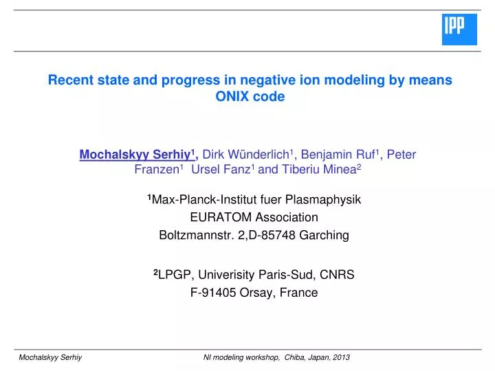
Recent state and progress in negative ion modeling by means ONIX code. Mochalskyy Serhiy 1 , Dirk Wünderlich 1 , Benjamin Ruf 1 , Peter Franzen 1 Ursel Fanz 1 and Tiberiu Minea 2. 1 Max-Planck-Institut fuer Plasmaphysik EURATOM Association Boltzmannstr . 2,D-85748 Garching.

Recent state and progress in negative ion modeling by means ONIX code
E N D
Presentation Transcript
Recent state and progress in negative ion modeling by means ONIX code Mochalskyy Serhiy1, Dirk Wünderlich1, Benjamin Ruf1, Peter Franzen1 Ursel Fanz1 and Tiberiu Minea2 • 1Max-Planck-Institut fuerPlasmaphysik • EURATOM Association • Boltzmannstr. 2,D-85748 Garching • 2LPGP, Univerisity Paris-Sud, CNRS • F-91405 Orsay, France
Outline Introduction Code improvement Code validation Code benchmarking Realistic parameters Results Conclusions and future plans 2/32
The goal is to produce negative ion 48A H- (40A D-) (j~20mA/cm2) beam with INI/Ie~1 at low pressure 0.6pa during continuous 1 hour operation. Introduction: Negative ion plasma source system NI surface and volume production Extraction region Expansion region Driver 3/32
3D Particle-in-Cell Monte Carlo Collision electrostatic code specially developed for modeling NI production and following extraction from ITER NBI plasma source. • Fully paralellized via MPI using domain and particle decomposition techniques. • Able to deal with complex geometries as in the case of the extraction aperture. Introduction:ONIX (Orsay Negative Ions eXtraction) code Plasma grid Extraction grid 19 mm Simulation domain 14 mm 14 mm 4/32
Code improvement:Second order charge and E field assignment routine (1) First order Potential distribution Second order Potential distribution P (V) P (V) P (V) P (V) E(x) distribution E(x) distribution Ex (V/cm) Ex (V/cm) Ex (V/cm) Ex (V/cm) y (mm) x (mm) 5/32
Code improvement:Second order charge and E field assignment routine (2) First order Second order E(y) distribution E(y) distribution Ey (V/cm) Ey (V/cm) Ey (V/cm) Ey (V/cm) y (mm) x (mm) Ex ( E(z) distribution E(z) distribution Ez (V/cm) Ez (V/cm) Ez (V/cm) Ez (V/cm) y (mm) x (mm) 6/32
Code improvement:NI flux from PG (1) – injection method Trajectories of NI Flux at the given x plane Z (mm) y (mm) 7/32
Code improvement:NI flux from PG (2) – extracted electron and NI current Extracted NI current Extracted e current 8/32
Code improvement:NI flux from PG (3) – potential well in vicinity to PG New routine (random injection, random energy 0.01 - 1eV) New routine (random injection, 1eV) Old routine (normal injection, 1eV) Potential (V) Potential (V) Potential (V) y (mm) y (mm) y (mm) PG PG PG X (mm) X (mm) X (mm) 9/32
Code improvement: Addition to the simulation H3+ ion and H- in the volume H3+ density nH3+ (m-3) Extracted electron and NI current PG y (mm) Y (mm) PG H- from volume density nH3+ (m-3) PG Y (mm) PG 10/32
Code validation: Potential well test in simplified model Potential well test Potential sheath test Potential (V) Density (m-3) X (mm) X (mm) 11/32
Code validation: Potential well test in simplified model (2) Negative bias Potential (V) 0V -5V Potential (V) -10V x (mm) Positive bias Potential (V) 10V FIG. 10. Schematic of possible steady-state plasma potential profiles near a positively biased plate. Curve A corresponds to a large plate. Curve B corresponds to a small plate. Noah Hershkowitzb, Phys. Of Plasma (2005) 055502 5V Potential (V) 0V 0V x (mm) 12/32
Code validation: different mesh size (real domain) Potential (V) Potential (V) y (mm) y (mm) PG PG x (mm) x (mm) Potential (V) Electrons current y (mm) PG x (mm) 13/32
Code benchmark: ONIX vs KOBRA3D 2 completely different codes with different approaches: 1) ONIX – uses plasma parameters (density, temperature,…) to calculate the extraction current and meniscus shape; 2) KOBRA 3D –uses the extraction current to calculate the potential and meniscus shape PI extraction test (2 runs) Density 0.8, 1.6,*1017 m-3 , e:100%, H+:100%; Te=2eV, TPI=1eV Extraction potential: -5kV; B field is switch off, no collisions PG aperture 8 mm diameter 14/32
Code benchmark: ONIX vs KOBRA3D (2) PI extraction test (4 runs) Density 0.8, 1.6, 2.4, 3.2*1017 m-3 , e:100%, H+:100%; Te=2eV, TPI=1eV Extraction potential: -5kV; B field is switch off, no collisions PG aperture 8 mm diameter and 4mm length (2mm to PG knife and 2 mm after) KOBRA3D ONIX 15/32
Realistic parameters: Magnetic field map Deflecting field Filter field vertical z direction axial x direction 16/32
Realistic parameters: Magnetic field map • Complete 3D magnetic field structure and thus 3D model is necessary to perform realistic simulation of NI extraction. PG Deflecting field Bz Filter field PG PG vertical z direction PG Bx axial x direction 17/32
Realistic parameters: Magnetic field map Deflecting field Filter field vertical z direction By axial x direction 18/32
Realistic parameters: Magnetic field map By Bx Bz 19/32
CRDS OES Probe measurements NI emission rate BACON Full 3D magnetic field map 3D field simulation Geometry of the plasma grid Engineering specification Realistic parameters: Plasma parameters in ONIX simulations ONIX n=3*1017m-3 ne=90%; nNI=10%, nH+=40%, nH2+=40%, nH3+=20% Te=2, TH-=0.1,TH+=0.8, TH2+=0.1, TH3+=0.1 (eV) jNI,PG=660A/m2 nH=1*1019m-3, TH=0.8eV nH2=4*1019, TH2=0.1eV 20/32
NI from the surface is dominant; • NI current from the inner surface of the PG is higher than one from outer side; • Co-extracted electron current ~3.5 times higher than total NI current in no PG bias test. Typical evolution of extracted NI currents Conical PG surface flat PG surface PG 21/32
Results:Limitation of the NI extraction Potential distribution in vicinity to PG Potential (V) y (mm) PG x (mm) 22/32
Results:Potential at the wall Emission rate ~250A/m2 (~-3V) Emission rate ~2000A/m2 (~-20V) PG y (mm) Potential (V) x (mm) Emission rate ~800A/m2 (~-13V) y (mm) PG Potential (V) x (mm) 23/32
Limitation of the NI extraction Results: NI density produced from the conical surface of PG Total NI density along domain Density (m-3) PG PG y (mm) y (mm) Density (m-3) PG PG x (mm) x (mm) NI density produced from the flat surface of PG NI density produced at the volume Density (m-3) PG y (mm) y (mm) Density (m-3) PG x (mm) x (mm) 24/32
Results:Ion –Ion plasma calculation (NI current) With B field No B field current (mA) current (mA) z vertical direction z vertical direction y horizontal direction y horizontal direction 25/32
Results:Ion –Ion plasma calculation (NI density distribution) With B field No B field y (mm) y (mm) Density (m-3) Density (m-3) x (mm) x (mm) y (mm) y (mm) Density (m-3) Density (m-3) x (mm) x (mm) 26/32
Results:Ion –Ion plasma calculation (e current) No B field With B field current (mA) current (mA) z vertical direction z vertical direction y horizontal direction y horizontal direction 27/32
Results:Ion –Ion plasma calculation (e density distribution) With B field No B field y (mm) y (mm) Density (m-3) Density (m-3) x (mm) x (mm) 28/32
Results:Ion –Ion plasma calculation (H+ density distribution - meniscus) No B field With B field y (mm) y (mm) Density (m-3) Density (m-3) x (mm) x (mm) 29/32
Results:Ion-ion plasma simulations (5 runs) NI current density e current density 30/32
Results:Meniscus shape for several ion-ion plasmas (5 runs) PG H+ density 95:5=e:NI (%) PG PG 25:75 PG PG 75:25 PG PG 5:95 PG PG 50:50 PG 31/32
Thank you for your attention Project is supported by the Alexander von Humboldt foundation 32/32