Download
1 / 16
160 likes | 373 Views
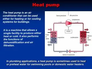
Operation of heat pump cycles. Jørgen Bauck Jensen & Sigurd Skogestad Department of Chemical Engineering Norwegian University of Science and Technology. The Gas Technology Center, NTNU-SINTEF / Norwegian Research Council. Overview . Simple cycles Complex cycles Design vs. operation Model

E N D
Operation of heat pump cycles Jørgen Bauck Jensen & Sigurd Skogestad Department of Chemical Engineering Norwegian University of Science and Technology The Gas Technology Center, NTNU-SINTEF / Norwegian Research Council
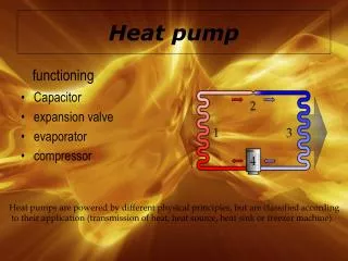
Overview • Simple cycles • Complex cycles • Design vs. operation • Model • MATLAB • Example • Conclusion and further work
Simple cycles • Examples: • Heat pumps • Air-conditions • Refrigerators Control objective 1 • Temperature Manipulated input: 1 (2) • Compressor on-off/speed • (Valve opening) Remaining DOF’s for optimization 0 (1) • Operating point given for fixed valve • How does the operating point change with disturbances? • Valve opening possible input • How can this improve operation?
Complex cycles • Examples • Liquefied Natural Gas (LNG) plants • Air separation processes Control objective: 1 • Temperature Manipulated inputs: 4 • Compressor speed • Valve openings • Composition Remaining DOF’s for optimization: 3 • What is optimal operation!? • Not easy to determine Pre-cooler for the mixed fluid cascade process (MFC)
Design vs. operation • Snøhvit-project in northern Norway • MFC process for cooling natural gas • Preliminary studies gives potential savings in the order of some percent compared to “optimal” design • Design:Objective function includes both investment and operational costs • Operation:Objective function depends only upon operational costs • Therefore (in some cases) :Optimal operation ≠ optimal design, also at design conditions!!
The model is a set of differential and algebraic equations (DAE) Differential equations Balance for mass, energy and volume Algebraic equations Thermodynamic state and property relations Equilibrium relations Mass and energy transfer Control volume balances Controllers and control elements Modeling (dynamic) • Purpose of model • Optimization • Control structure analysis • Dynamic simulations • Demands for model • Fast • Accurate • Robust • Problems • Dynamic two-phase heat exchangers • Solver
MATLAB • ODE set (ode15s) • Algebraic relations solved internally slows down the ode solver • DAE set (ode15s) • Good initial values needed because of algebraic equations • DAE set (ode15i) • Not tested • Fully implicit solver in MATLAB 7 • Also a function for initialization • Simulink (ode15s) • Nice interface where it is easy to add: • Control • Visualization • Tools for analysis • In theory easy to arrange states • Not possible to solve set of DAE (?)
CO2 Heat pump - Design • Design conditions • 22 °C inside • -5 °C outside • Minimum ΔT of 10 °C • 10 kW heat supply @ above specifications • Design • UA (cooler) = 590 W/K • UA (vaporizer) = 660W/K • Cv (valve) = 1,66∙10-6 m2 • Cv (cooler) = 1,79∙10-5 m2
Compressor Adiabatic 70% efficiency Cooler One-phase heat exchanger 6 control volumes Valve equation gives flow between control volumes Heat exchange to air in room at constant temperature Valve One-phase valve equation Isenthalpic Vaporizer Two-phase heat exchanger One control volume Equilibrium between the two phases Heat exchange to outside air at constant temperature CO2 Heat pump – Model
CO2 Heat pump - Control Constant valve opening: Case A • Control objective • Room temperature • Manipulated inputs • Compressor work • Valve opening • Disturbances • Air temperature (main disturbance) • Set point for room temperature • UA for the room (i.e.. opening a window) • Constraints • Valve opening • Compressor work • Pressures
CO2 Heat pump - Control Constant high pressure: Case B • Control objective • Room temperature • Manipulated inputs • Compressor work • Valve opening • Disturbances • Air temperature (main disturbance) • Set point for room temperature • UA for the room (i.e.. opening a window) • Constraints • Valve opening • Compressor work • Pressures
CO2 Heat pump – Result Optimal starting point: • Constant valve opening gives a maximum loss of 1% within ±10 degrees off design point • Easy to implement • Constant high pressure gives larger loss • Possible to find a variable that gives zero loss Fixed valve opening is a good self optimizing control variable!
CO2 Heat pump - Operation Optimal operating point • Constant room temperature • Optimal operating point • 23 bar LP (subcritical) • 90 bar HP (supercritical) • 0,9 mol/s circulation • 3,35 kW compressor • COP = 2,99 • Inaccurate UA values moves optimum • Designed for 50% • Optimal at 34% • Optimal pressure ratio sensitive to temperature out of heat exchangers • Verified with HYSYS model
CO2 Heat pump – Result Non-optimal starting point: Point 2 • Larger losses than from optimal starting point • Disturbance in one direction improves performance • Constant valve opening is still the best strategy in average Choice of self optimizing control variable does not depend on starting in optimal point!
Simple cycles Constant valve is a good self optimizing control variable Choice of self optimizing control variable is not dependent on starting in optimal point Optimization in operation Mostly thermodynamic studies are reported Important because design and operation are different in some cases Look into industrial complex cycles where small improvements are important Conclusion & further work
References • http://www.statoil.com/STATOILCOM/snohvit/svg02699.nsf?OpenDatabase&lang=en • S. Skogestad, I. J. Halvorsen and J. C. Morud, Self-optimizing control: The basic idea and Taylor series analysis, AIChE Annual Meeting, Miami Beach, 16-20 Nov. 1998, Paper 229c • The Gas Technology Center, NTNU-SINTEF • Norwegian Research Council Acknowledgements