Download
1 / 206
2.08k likes | 2.12k Views
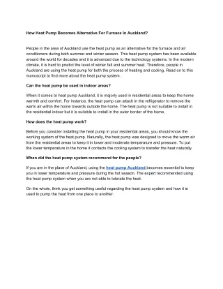
Discover the latest technology in heat pumps for ultimate climate control. Learn how they absorb energy efficiently down to -20º.

E N D
HEAT PUMPS • TOTAL ELECTRIC UNIT CAPABLE OF PROVIDING HEATING AND COOLING • MOVES HEAT WITH REFRIGERATION SYSTEM. • CURRENT TECHNOLOGY ALLOWS US TO ABSORB ENERGY FROM THE OUTDOOR AIR EFFICIENTLY, DOWN TO 20º.
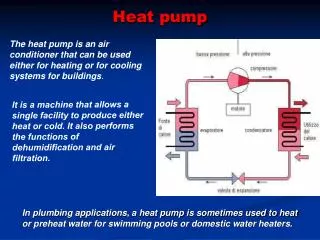
During the winter months the heat pump absorbs heat from the outdoor air. • Then releases the heat (energy) into the indoor air. • There is energy (heat) present to minus 460º. • Just as it is more efficient to move an object than it is to build or make one. It is more energy efficient to move heat, than generate it (depending on thermal/economic balance points).
Heat pumps are sized for the cooling demand of the application. • The heat pump will be the sole source of cooling for the application. It may be the only source of heat, depending on heating requirements. • Most areas of the country will also require an additional source of heat. This may be as little as a 5KW heat strip, or as much as a 80,000 BTU furnace. • We’ll look at this in more detail later.
HEAT PUMPS • COOLING SEASON • HEAT PUMP PERFORMS THE SAME AS ANY AIR CONDITIONING SYSTEM BY PICKING UP HEAT FROM THE SPACE TO BE CONDITIONED AND REJECTING IT OUTDOORS
HEAT PUMPS • HEATING SEASON • UNIT ABSORBS HEAT FROM THE OUTDOOR AIR AND MOVES IT TO THE CONDITIONED SPACE • REVERSE-CYCLE AIR CONDITIONERS
HEAT PUMPS • CLASSIFIED BY: THE SOURCE OF HEAT DURING THE HEATING CYCLE AND THE MEDIUM TO WHICH THE HEAT IS TRANSFERRED • AIR-TO- AIR • WATER-TO-AIR
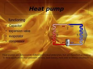
INSIDE THE HEAT PUMP • COMPRESSOR CAPABLE OF OPERATING AT LOW OUTDOOR TEMPERATURES • INDOOR / OUTDOOR COIL DESIGN • METERING DEVICE FOR INDOOR / OUTDOOR COIL • REVERSING VALUE ( 4-WAY VALUE ) • ACCUMULATOR • CRANKCASE HEATER • AUXILIARY HEAT • EMERGENCY HEAT • DEFROST CYCLE
HEAT PUMP • ACCUMULATOR • CLIMATUFF - PART OF COMPRESSOR SHELL • LOCATED IN SUCTION LINE BETWEEN THE COMPRESSOR AND REVERSING VALUE • WHY HAVE ONE? • MOST IMPORTANT: • HEATING CYCLE - COLD TEMPERATURES, OUT DOOR COIL MAY NOT BE ABLE TO EVAPORATE ALL THE REFRIGERANT • END OF DEFROST CYCLE • LIQUID CARRYOVER WILL BE CAUGHT BY THE ACCUMULATOR TO PREVENT COMPRESSOR DAMAGE
WHAT MAKES A HEAT PUMP UNIQUE • SPECIAL COMPRESSOR • MUCH HIGHER COMPRESSION RATIO • MOST SEVERE APPLICATION • HEAT PUMP COILS • ALTERNATELY FUNCTION AS EVAPORATOR AND CONDENSER • MUST TOLERATE CHARGE IMBALANCE • OUT DOOR COIL MUST BE DESIGNIED FOR EASY DEFROST
HEAT PUMP • CRANKCASE HEATER • LOCATED ON COMPRESSOR, OLDER SYSTEMS USED COMPRESSOR WINDINGS. • RAISES TEMPERATURE OF OIL SO THAT THE ABSORPTION OF REFRIGERANT INTO THE COMPRESSOR IS KEPT TO A MINIMUM
COOLING CONDITION INDOOR COIL SAT. SUCT. T. 41F ENT. AIR T. 76F 4-WAY VALUE SUCT. P. 70 PSIG SUCT. T. 52F SUPERHEAT 11F METERING DEVICE SUBCOOLING 10F DISCHARGE PRESSURE 260 PSIG OUTDOOR COIL SAT. COND. T. 120F ENT. AIR T. 90F COMPRESSOR
HEATING CONDITIONS INDOOR COIL SAT. COND. T. 95F ENT. AIR T. 70F 4-WAY VALUE METERING DEVICE SUBCOOLING 10F METERING DEVICE SUBCOOLING 10F SUCT. P. 43 PSIG SUCT. T. 35F SUPERHEAT 10F DISCHARGE PRESSURE 182 PSIG OUTDOOR COIL SAT. SUCT. T. 20F ENT. AIR T. 45F COMPRESSOR
HEAT PUMP • TOTAL HEAT REJECTED EQUALS HEAT ABSORBED + HEAT OF COMPRESSOR
HEAT PUMP THE REVERSING VALUE CONTROLS THE DIRECTION THE REFRIGERANT FLOWS
COOLING CONDITION INDOOR COIL SAT. SUCT. T. 41F ENT. AIR T. 76F 4-WAY VALUE SUCT. P. 70 PSIG SUCT. T. 52F SUPERHEAT 11F METERING DEVICE SUBCOOLING 10F DISCHARGE PRESSURE 260 PSIG OUTDOOR COIL SAT. COND. T. 120F ENT. AIR T. 90F COMPRESSOR
HEATING CONDITIONS INDOOR COIL SAT. COND. T. 95F ENT. AIR T. 70F 4-WAY VALUE METERING DEVICE SUBCOOLING 10F METERING DEVICE SUBCOOLING 10F SUCT. P. 43 PSIG SUCT. T. 35F SUPERHEAT 10F DISCHARGE PRESSURE 182 PSIG OUTDOOR COIL SAT. SUCT. T. 20F ENT. AIR T. 45F COMPRESSOR
Heat pump Thermostats • Thermostats with adjustable heat anticipation need to have it adjusted for proper operation!
ODA F HEAT COOL OFF O HA CA BAYSTAT239 OR 240 HEAT PUMP THERMOSTAT NORM Y C1 TS RHS-1 COOL H1 X2 HEAT AUTO FAN G SM-2 ON RHS-2 NORM T TSH W BL U RD B R
ODA Fault Indication Light F HEAT COOL OFF O HA CA NORM Y C1 TS RHS-1 COOL H1 X2 HEAT AUTO FAN G SM-2 ON RHS-2 NORM T TSH W BL U RD B R
Fault Indication Light F HEAT COOL OFF SOV Energized In Cooling O HA CA NORM Y C1 TS RHS-1 COOL H1 X2 HEAT AUTO FAN G SM-2 ON RHS-2 NORM ODA T TSH W BL U RD B R
ODA Fault Indication Light F HEAT COOL OFF SOV Energized In Cooling O HA CA Brings On Compressor In Both Heating And Cooling NORM Y C1 TS RHS-1 COOL H1 X2 HEAT AUTO FAN G SM-2 ON RHS-2 NORM T TSH W BL U RD B R
ODA Fault Indication Light F HEAT COOL OFF SOV Energized In Cooling O HA CA Brings On Compressor In Both Heating And Cooling NORM Y C1 TS RHS-1 COOL H1 X2 Energizes Auxiliary Heat When Unit Is In Defrost HEAT AUTO FAN G SM-2 ON RHS-2 NORM T TSH W BL U RD B R
ODA Fault Indication Light F HEAT COOL OFF SOV Energized In Cooling O HA CA Brings On Compressor In Both Heating And Cooling NORM Y C1 TS RHS-1 COOL H1 Energizes Auxiliary Heat When Unit Is In Defrost X2 HEAT AUTO FAN G SM-2 Brings On Indoor Fan ON RHS-2 NORM T TSH W BL U RD B R
ODA Fault Indication Light F HEAT COOL OFF SOV Energized In Cooling O HA CA Brings On Compressor In Both Heating And Cooling NORM Y C1 TS RHS-1 COOL H1 Energizes Auxiliary Heat When Unit Is In Defrost X2 HEAT AUTO FAN G SM-2 Brings On Indoor Fan ON RHS-2 NORM Part of Heat Anticipation Circuit (Used with Trane Electro-Mechanical T’stats T TSH W BL U RD B R
ODA Fault Indication Light F HEAT COOL OFF SOV Engerized In Cooling O HA CA Brings On Compressor In Both Heating And Cooling NORM Y C1 TS RHS-1 COOL H1 Energizes Auxiliary Heat When Unit Is In Defrost X2 HEAT AUTO FAN G SM-2 Brings On Indoor Fan ON RHS-2 NORM Part of Heat Anticipation Circuit (Used with Trane Electro-Mechanical T’stats T TSH This Is The Second Stage-Brings On The Electric Heat W BL U RD B R
ODA Fault Indication Light F HEAT COOL OFF SOV Engerized In Cooling O HA CA Brings On Compressor In Both Heating And Cooling NORM Y C1 TS RHS-1 COOL H1 Energizes Auxiliary Heat When Unit Is In Defrost X2 HEAT AUTO FAN G SM-2 Brings On Indoor Fan ON RHS-2 NORM Part of Heat Anticipation Circuit (Used with Trane Electro-Mechanical T’stats T TSH This Is The Second Stage-Brings On The Electric Heat W BL U Functions As An Internal Connection For The Blue Light RD B R
ODA Fault Indication Light F HEAT COOL OFF SOV Engerized In Cooling O HA CA Brings On Compressor In Both Heating And Cooling NORM Y C1 TS RHS-1 COOL H1 Energizes Auxiliary Heat When Unit Is In Defrost X2 HEAT AUTO FAN G SM-2 Brings On Indoor Fan ON RHS-2 NORM Part of Heat Anticipation Circuit (Used with Trane Electro-Mechanical T’stats T TSH This Is The Second Stage-Brings On The Electric Heat W BL U Functions As An Internal Connection For The Blue Light RD B This Is The Common Side Of The Transformer R
ODA Fault Indication Light F HEAT COOL OFF SOV Engerized In Cooling O HA CA Brings On Compressor In Both Heating And Cooling NORM Y C1 TS RHS-1 COOL H1 Energizes Auxiliary Heat When Unit Is In Defrost X2 HEAT AUTO FAN G SM-2 Brings On Indoor Fan ON RHS-2 NORM Part of Heat Anticipation Circuit (Used with Trane Electro-Mechanical T’stats T TSH This Is The Second Stage-Brings On The Electric Heat W BL U Functions As An Internal Connection For The Blue Light RD B This Is The Common Side Of The Transformer This Is The Other Side Of 24 Volts From The Transformer R
ODA F HEAT COOL OFF O HA CA BAYSTAT239 OR 240 HEAT PUMP THERMOSTAT NORM Y C1 TS RHS-1 COOL H1 X2 HEAT AUTO FAN G SM-2 ON RHS-2 NORM T TSH W BL U RD B R
ODA G INDOOR UNIT B W1 R F HEAT COOL OFF O HA CA NORM Y C1 TS RHS-1 COOL H1 X2 HEAT AUTO FAN G SM-2 ON RHS-2 NORM T TSH W BL U RD B R
ODA G INDOOR UNIT B W1 R F HEAT COOL OFF O HA CA NORM FAN ON - ON Y C1 TS RHS-1 COOL H1 X2 HEAT AUTO FAN G SM-2 ON RHS-2 NORM T TSH W BL U RD B R
G INDOOR UNIT B W1 R BAYSTAT240A F HEAT COOL COOLING ON FAN - AUTO OFF O HA CA NORM Y C1 TS RHS-1 COOL H1 X2 HEAT AUTO FAN G SM-2 ON RHS-2 NORM ODA T TSH W BL U RD B R COOLING ON FAN - AUTO
OUTDOOR UNIT Defrost Board R Y R/W X2 O BL BL Y O ODS-A G INDOOR UNIT B W1 R BAYSTAT240A F HEAT COOL OFF O HA CA NORM Y C1 TS RHS-1 COOL H1 X2 HEAT AUTO FAN G SM-2 ON RHS-2 NORM ODA T TSH W BL U RD B R COOLING ON FAN - AUTO
F HEATING - ON - FIRST STAGE FAN - AUTO HEAT COOL OFF O HA CA NORM Y C1 TS RHS-1 COOL H1 X2 HEAT AUTO FAN G SM-2 ON RHS-2 NORM ODA 15 TO 22 VOLTS (T) FROM ODS-A TO (R) T TSH W BL U RD B R
BAYSTAT240A F HEAT COOL OFF O HA CA NORM Y C1 TS RHS-1 COOL H1 X2 HEAT AUTO FAN G SM-2 ON RHS-2 NORM ODA T TSH W BL INDOOR UNIT U G RD B B W1 R R
OUTDOOR UNIT BAYSTAT240A Defrost Board F HEAT COOL OFF O HA CA R NORM Y C1 TS Y RHS-1 R/W COOL H1 X2 X2 HEAT O AUTO BL FAN G SM-2 BL ON RHS-2 Y NORM O ODA T TSH ODS-A W BL INDOOR UNIT U G RD B B W1 R R
HEATING - ON - 2ND STAGE FAN - AUTO F HEAT COOL OFF O HA CA NORM Y C1 TS RHS-1 COOL H1 X2 HEAT AUTO FAN G SM-2 ON RHS-2 NORM ODA 15 TO 22 VOLTS (T) FROM ODS-A TO (R) T TSH W BL U RD B R
F HEAT COOL OFF 24 VOLT S (O) FROM DEF. BRD O HA CA NORM Y C1 TS RHS-1 24 VOLT S (X2) FROM DEF. BRD COOL H1 X2 HEAT AUTO FAN G SM-2 ON RHS-2 NORM ODA 15 TO 22 VOLTS (T) FROM ODS-A TO (R) T TSH W BL U RD B R
BAYSTAT240A HEATING ON EMERG. HTG (OPERATES 1.5° BELOW SETPOINT) FAN - AUTO F HEAT COOL OFF O HA CA NORM Y C1 TS RHS-1 COOL H1 X2 HEAT AUTO FAN G SM-2 ON RHS-2 NORM ODA T TSH W BL INDOOR UNIT U G RD B B W1 R R
WHAT IS COOLING DROOP? • Cooling droop is caused by the cooling anticipator heating up during the off cycle, causing the t’stat to come on sooner, to help overcome the thermal lag of the system. • This also provides night time cooling that helps keep humidity under control
DROOP (cont’) • Then there is Heating Droop. • Heating Droop moves the temperature in the wrong direction. To compensate for this, the “T” circuit is added.
WHAT DOES THE “T” CIRCUIT HAVE TO DO WITH ANYTHING? • The “T” circuit is a heat anticipation circuit that adds heat to the thermostat to slow down thermostat response, and removes heat to speed up the response.
“T” Circuit • As the outdoor temperature drops, the resistance in the “T”, actually a thermistor (ODS-A), goes up. • The higher the resistance, the less voltage is supplied to the resistor (ODA) located inside the thermostat. • The less voltage to the ODA, the colder the t’stat thinks it is.
DEFROST THERMISTOR RESISTANCE 10000 9000 8000 7000 6000 5000 RESISTANCE 4000 3000 2000 1000 75 115 35 -40 0 OUTDOOR TEMPERATURE
ODS-A .0034 A -20°F 4000 3000 13.6 V 10.4 V .047 W .036 W
ODS-A .0034 A -20°F 4000 3000 ODS-A 13.6 V 10.4 V .047 W .036 W .0048 A 2000 0°F 3000 9.6 V 14.4 V .046 W .069 W
ODS-A .0034 A -20°F 4000 3000 ODS-A 13.6 V 10.4 V .047 W .036 W .0048 A 2000 0°F 3000 ODS-A 9.6 V 14.4 V .046 W .069 W .0063 A 30°F 800 3000 5 V 19 V .031 W .119 W
ODS-A .0034 A -20°F 4000 3000 ODS-A 13.6 V 10.4 V .047 W .036 W .0048 A 2000 0°F 3000 ODS-A 9.6 V 14.4 V .046 W .069 W .0063 A 30°F 800 3000 ODS-A 5 V 19 V .031 W .119 W .0073 A 70°F 300 3000 2.2 V 21.8 V .013 W .159 W
B T T DEFROST BOARD DURING DEFROST K2 OD Motor 230 VOLTS BR/BL T’STAT R R Y Y K1 F RD/W X2 BK O O T BL COMPR Y SOV O AMB. SENSORS COL