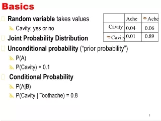
LEEM Basics
LEEM Basics. Frank-J. Meyer zu Heringdorf - Universit ät Duisburg - Essen - meyerzh@uni-essen.de. 1962 Invention by Ernst Bauer Glass-Based Vacuum Apparatus 1985 First Operational LEEM Instrument Telieps and Bauer 1991 IBM LEEM-I Tromp and Reuter This Instrument Now in Essen

LEEM Basics
E N D
Presentation Transcript
LEEM Basics Frank-J. Meyer zu Heringdorf - Universität Duisburg-Essen - meyerzh@uni-essen.de Frank-J. Meyer zu Heringdorf
1962 Invention by Ernst Bauer Glass-Based Vacuum Apparatus 1985 First Operational LEEM Instrument Telieps and Bauer 1991 IBM LEEM-I Tromp and Reuter This Instrument Now in Essen 1993 Elmitec LEEM Former Coworkers of E. Bauer 1998 IBM LEEM-II PEEM and LEEM History Since Then: LEEM and PEEM has Gained Inreasing Importance: Today More Than 30 Instruments Worldwide (2 in Essen)
Outline • Photoemission Electron Microscopy • Electron Optics • Photoemission • Example • Low Energy Electron Microscopy • Electron Optics • Diffraction Techniques • Imaging Modes • Outlook
Magnetic Lenses • As Lenses for Optics • Focal Length • A Few Differences • Image Rotation • Only Convex Lenses • Quality much Worse ! Objective Lens of new S-PEEM in Essen
Basic PEEM Optics • Photoemission • “Creates“ Electrons • Bias Voltage • Reduces Angle of Photoemitted Electrons, thus increases Numerical Aperture • Projector Lenses • Magnify Image on the Screen • Camera • Records Image to Computer or Video Tape ln-w3.polycnrs-gre.fr/themes/ dichro/PEEM-fr.html
Photoemission of Electrons • Surface Illumination • Typical: HG Lamp (5eV) but also possible Synchrotron Light (ELETTRA, BESSY, CERN) or Laser Light (ESSEN) • Electron Emission • Angles depend on Band-Structure of Material and can be quite high. 134.96.28.159/methoden/methoden.html
PEEM Contrast Mechanism • Contrast either by Work Function or DOS • Pentacene: 5 Benzene Rings • Contrast Changes During Deposition • FoV = 65µm 1 Layer 2 Layers 3 Layers F.-J. Meyer zu Heringdorf et al., NATURE 412 (517), 2001
LEED Screen Analyzer LoadLock Camera Prep. Chamber MainChamber Hg Lamp Evaporator Spectroscopic PEEM in Essen http://www.physik.uni-essen.de/SFB616 • ELMITEC PEEM III • Energy Analyzer • LN2 Sample Cooling • Preparation Chamber • LEED, Auger
LEEM Capabilities Electron Energy 0 - 100 eV Field of View LEEM: 1 - 20 µm PEEM: up to 65 µm Resolution In Plane: 5 nm Vertical: Atomic Steps Visible in situ Growth, Etching RT - 1000°C
Electron Gun Visible High Linearity Spots move with Energy Low Energy Electron Diffraction LEED LEEM http://www.vgsysj.co.jp/sipic.jpg No Apparent Electron Gun Secondary Electrons Spots Don‘t Move
Microdiffraction, µ-Spot LEED • LEED on Small Areas • Pentacene on Si • Polycrystalline Layer
Electron Energy is 0eV Electrons Return Before they Hit the Sample Contrast created by outer Potential Workfunction Image appears Blurred Mirror Imaging of Si(111)
Bright Field Imaging of Si (111) • Different Reflectivity of (1x1) and (7x7) • Reflectivity Energy Dependent • Contrast Reversal Dependent on • Imaging Conditions
Phase Contrast Imaging • Analogue LEED • Electrons from Different Terraces have a Phase Shift at Out-of-Phase Conditions • Localized Phase Shift • Defocusing of the Image turns Steps into Dark Lines, i.e. Centers of Destructive Interference.
(2x1) and (1x2) Domains Orientation Changes at each Step The Si (100) Surface
Creator of the LEED Spots Lights up in Bright Dark Field Imaging • The Rest of the Surface Remains Dark
Au on Si (111) Dominant Low-Coverage Reconstruction: Au-(5x2) Higher Coverage: (5x2) is replaced by sqrt 3 x sqrt 3 Simultaneous Dark-Field Imaging 5x2 5x2 7x7 7x7 5x2 Nagao et al., Phys. Rev. B. 57, 10100 (1998)
Simultaneous Dark-Field Imaging One Bright-Field Image 3 Dark Field Images Assign Colors to the DF Images and Overlap Them
LEEM and PEEM Powerful Surface Imaging Technique In Situ Imaging, During Growth Possible Similar TEM for Bulk, but for Surfaces Many Different Contrast Mechanisms for Imaging of different Aspects More Contrast Mechanisms than Mentioned Here: Energy Analyzer and Synchrotron: Spatially Resolved XPS, UPS, Auger, XPEEM Spinpolarized Gun Allows Magnetic Imaging Conclusions & Outlook Thanks to: P. Kury, Chr. Seifert, D. Thien, M. Horn-von Hoegen, R. Tromp