GIS Data: Types and Structures
GIS Data: Types and Structures. Geographic Data: Concepts, File Formats, Topology Anatomy of Spatial File Formats shapefile, geodatabase, coverage Coordinate Systems and Projections Spring 2008. Geographic Data: Classic Approach. Two components of geographic data

GIS Data: Types and Structures
E N D
Presentation Transcript
GIS Data: Types and Structures Geographic Data: Concepts, File Formats, Topology Anatomy of Spatial File Formats shapefile, geodatabase, coverage Coordinate Systems and Projections Spring 2008 GISC 6382 Applied GIS UT-Dallas Briggs
Geographic Data: Classic Approach • Two components of geographic data • Spatial Data: representations of geographic features associated with real-world locations • Stored in files and managed by the GIS software • Attribute Data: descriptive information • stored in tables and managed by an RDBMS (relational database managemnt system) (originally ESRI’s proprietray Info system, but now any standard commercial system such as Access, Oracle, SQL Server ) • Two formats for geographic data • Raster data • Rectangular array of cells or pixel • Vector data: three feature types • points/nodes (single x,y locations) • lines/arcs (linear string of x,y locations) • areas/polygons (closed string of x,y locations) GISC 6382 Applied GIS UT-Dallas Briggs
Geographic Data: Another (object-oriented) View Object View • The real world is a series of entities located in space (houses, poles, soil types) • Some locations have values, others are null • An object is a digital representation of an entity, with three types • Point objects • Line objects • Area objects • The same entity can be represented at different scales by different object types: the multi-representation problem • Behavior can be associated with objects thus they can change over time Field View • Real world properties vary continuously over space; • every place has a value • represent as raster dataor as vector data in a TIN (triangulated irregular network Object versus Field View • Not as distinct as first appears • If the value is a categorical or integer variable, then places with the same value (e.g. soil type) can be grouped--which give us area objects! • The world is how we decide to look at it! From O’Sullivan and Unwin GISC 6382 Applied GIS UT-Dallas Briggs
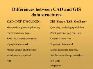
File Formats for Vector Spatial Data Coverage:vector data format introduced with ArcInfo in 1981 • multiple physical files (12 or so) in a folder • proprietary: no published specs & ArcInfo required for changes • Can be “exported” to a single E00 (E-zero-zero) file for transfer Shape ‘file’:vector data format introduced with ArcView in 1993 • comprises several (at least 3) physical disk files (with extension of .shp, .shx, .dbf), all of which must be present • openly published specs so other vendors can create shape files Geodatabase: new format introduced with ArcGIS 8.0 in 2000 • Proprietary, next generation spatial data model • Can be saved in several different physical formats (as of 9.2) • File based, MS Access based, commercial DBMS based • Versions available which support multi-user editing and replication Shapefiles are the simplest and most commonly used format. Used them in GIS Fund. Will use Geodatabases in Applied GIS (and some coverages). GISC 6382 Applied GIS UT-Dallas Briggs
Old Model: Geo-relational Database the old “classic” environment coverages in proprietary INFO database Raster data (in GRIDS) and 3-D data (in TINS) kept in separate, proprietary files shapefiles use openly published dbIV database (readable by Excel) Based on points, lines, polygon model Attribute data kept in separate databases and must be combined with coverages or shapefiles for spatial applications New Model: Geodatabase Replacement for coverages, with support for: Simple features: points, lines polygons Complex features: real world entities modeled as objects with properties, behavior, rules, & relationships Three Formats (as of 9.2): MS Access-based Personal Geodatabase (8.0>) Single-user editing, multiple read-only users Stored as one .mdb (Access) file Max 2GB total & 250,000 features per layer (effective max is 250-500MB) File-based Geodatabase (9.2>) Single-user editor, many read-only users Faster and more efficient than personal gdb. Unix and Microsoft supported Max 1 TB (256 TB for raster) SDE-based Geodatabase Personal (4), Workgroup (10) and Enterprise (??) versions Multi-user simultaneous editing via versioning and long transactions uses standard db: ORACLE, SQL Server, etc Attribute and spatial data in same database GIS User SDE db Database Environments
Geodatabase Features Grids Images Coverages Shapes Relationships Tables Tins Rules Tables Grids Images GIS Data ModelsFile-based and “Databased” Workspace One Repository Source: ESRI, Inc. GISC 6382 Applied GIS UT-Dallas Briggs
Concept of Topology • Topology distinguishes GIS data models from non-topological data models supported by many CAD, mapping and graphics systems • Topology refers to knowledge about relative spatial positioning of features. • knowledge about how features are connected and which features are adjacent to each other. • Can be viewed as a mathematical procedure that determines spatial relationships and properties, including: • The three Cs • Connectivity (US 75 connects to IH 45) • Congruency--same location (Red River & TX/OK border) • Contiguity--adjacency or “next door” (TX & OK) • Lengths of arcs and the areas of polygons GISC 6382 Applied GIS UT-Dallas Briggs
Topology Rules for Coverages:the classic view of topology • Each arc has a beginning node and an ending node - this determines directionality. Directionality is determined during digitizing. • Actual direction is important only if your application requires directional modeling. • Arcs connect to other arcs at nodes • Nodes must be present wherever arcs join or cross • Connected arcs form polygon boundaries • arc coordinates are stored only once because two adjacent polygons share the common arc between them. • Arcs have polygons on their left and right sides The next three slides illustrate this GISC 6382 Applied GIS UT-Dallas Briggs
Topology Concept I: Arc-node topology • Nodes are the end-points of arcs. Arc-node topology keeps track of which arcs are connected to other arcs through shared nodes X It defines length, direction, and connectivity for arcs. The from-node is an arc’s starting point; the to-node is its ending point. • They are determined as you digitize your data. • You can see the from-node and to-node whenever you list attribute records for a coverage containing lines. • Arcs connect if they share a node. GISC 6382 Applied GIS UT-Dallas Briggs
Topology Concept II: Polygon-arc topology • Polygon-arc topology expresses the relationship between the arc features and the polygon features for which the arcs create boundaries. It defines area and adjacency. Arcs or a set of arcs that form a closed figure define the area of a polygon. Two polygons are adjacent if they share an arc. Polygons are stored as a list of arcs to avoid redundancy. GISC 6382 Applied GIS UT-Dallas Briggs
Topology Concept III Left-right topology • Left-right topology refers to contiguity -- how polygons are associated with their neighboring polygons. Each arc has a list of which polygons are on the right side and which are on the left side. Commands in Arc/INFO use this information to determine from one polygon what the adjacent polygons are: 1 5 4 2 6 7 3 GISC 6382 Applied GIS UT-Dallas Briggs
Topology: Coverages v. Geodatabase v. Shapefiles Coverages (classic view of topology) • Topology is a property of the data itself • Applying Topology potentially changes the data file (coverage) via Clean (location of points) and Build (table structure) commands • A single coverage may have multiple geographic data types (points and lines, polygons and lines, but not points and polygons) Geodatabase(new view introduced with ArcGIS 8.3) • Topology is a set of rules selectively applied by the user ( 28 or so currently defined) • Does not alter the data file (feature class), unless user chooses to ‘fix’ violations • Topology saved as a relationship class within a geodatabase feature dataset • A feature class contains only one geographic data type (point or line or polygon), but all can be related together by a topology relationship class providing they are in the same feature dataset Shapefiles • share some similarities with coverages but are not fully topological • May need to covert to coverages for some analyses. Discuss topology for coverages later today and for geodatabases later in the course. GISC 6382 Applied GIS UT-Dallas Briggs
Anatomy of Spatial File Formats Shapefile Geodatabase Coverage • The following two diagrams show how geographic files appear in: • ArcCatalog • Windows Explorer • We will refer back to these as we discuss each of these file formats. GISC 6382 Applied GIS UT-Dallas Briggs
Personal Geodatabase Feature data set Feature class (feature type = polygon) Feature class (feature type = arc) In a gdb, feature class can have only one feature type. Coverage (= feature class) Feature type (arc) Feature type (point) Feature type (polygon) Feature type (point) A coverage can have multiple feature types-now viewed as a shortcoming. Coverage (= feature class) Feature type (arc) Feature type (point) Locator (table) Raster Shapefile Shapefile Spatial File Formats—example ArcCatalog View Tracts feature class table (attributes in columns) Features (rows) Feature ID (key field) Feature type Secondary or Foreign key
Spatial File Formats: NT Explorer View Info ‘master’ folder for AVCAT workspace Tracts coverage Trans coverage Locator (table) Personal Geodatabase Raster Tracts shapefile Trans shapefile GISC 6382 Applied GIS UT-Dallas Briggs
Shapefiles • openly published structure for spatial data (Coverages & Geodatabases are proprietary) • Partially an attempt (successfully!) by ESRI to make “their” format the industry standard • much simpler than coverages: rather than multiple folders and files, three main files with same name (road) but different extensions, e.g. • road.shp road.shx road.dbf • Attribute (feature) data stored in dBase (.dbf) file • Can be edited in Excel (or other) but do not change the number of rows • If you add columns, may need to change “refers to” definition via Insert/Name/Define • Files can be dragged, dropped, cut and pasted into other folders -- providing the complete file set is moved. GISC 6382 Applied GIS UT-Dallas Briggs
Geodatabase (gdb) File Structure GISC 6382 Applied GIS UT-Dallas Briggs
Geodatabase (gdb) Feature (vector) datasets Spatial Reference Object classes and subtypes Feature Classes and subtypes Relationship classes Network Topology Planar topology Domains Validation Rules Raster Datasets rasters TIN (3-D) datasets nodes, edges, faces Locators addresses x,y locations Zip codes place names route locations Geodatabases may contain: feature datasets, raster datasets, TIN datasets, locators Feature datasets contain vector data All data in a single feature dataset share a common spatial reference system Similar Objects (e.g. Jane Blow, land owner) are instances of object classes (e.g. land owners) and have no spatial form. Features and feature classes are spatial objects (e.g. land parcels) which are similar and have same spatial form (e.g. polygon) Object (or feature) classes are the tables, and objects (or features) are the rows of the table Attributes are in the columns of the table Subtypes are an alternative to multiple object (or feature) classes (e.g. ‘concrete’, ‘asphalt’, ‘gravel’ road subtypes): think of subtype as the most significant classification variable (attribute) in the class table Domains define permitted data values. Topology is saved as a relationship between the feature classes in the feature dataset. Anatomy of a Geodatabase
Object or Feature class=Table Object or feature = row Attribute = column Organizing Information: Classes Object Classes a set ofnon-spatial entities with similar characteristics e.g. owners of property Feature Classes a set of spatial entities with similar characteristics e.g. property parcels Classes are represented in Tables which are physically stored in the computer system in one or more files Key Field = attribute which uniquely identifies each feature or object GISC 6382 Applied GIS UT-Dallas Briggs
Feature classes (FC), feature datasets (fds) and subtypes • feature datasets (fds) are “spatial folders” which contain feature classes (spatial data sets, such as land parcel file or street file) • All feature classes in a fds must have the same spatial reference system, but may have different topology (can have points and lines and polygons in same fds) • Organize by thematic similarity e.g transportation • If you wish to create topology, must be in same fds • If they share geometry (street forms political boundary), should be in same fds • If you create a geometric network (e.g. to model water flow) must be in same fds • Security (read/write permissions, etc..) applied at the fds not the fc level!!!! • feature classes are spatial data setscontaining geographic features (e.g. land parcels): a table with spatial data • Data in FC must have same topology type (all points, all lines, all polygons) • Water feature class with lakes (polygon) and streams (line) not permitted • Minimizing the number of feature classes improves performance • Use different feature classes only when attributes are significantly different • Use roads feature class rather than freeway, arterial, streets feature classes • Use subtype to differentiate freeway, arterials, streets (all have similar attributes) • Subtypes are “subclasses” within a feature class that allow you to further distinguish objects without creating new feature classes • based on a single column’s values (must be integer or long integer) • Same subtype has similar attribute values and behaviors • Use where attributes are the same across all subtypes
Attribute Data Types: Geodatabase • For every attribute field, must select a data type • Each RDBMS stores data slightly differently • ESRI generic data types will translate into closest RDBMS equivalent • Values given below may differ with RDBMS used ESRI Generic Data Types String: text field. Be sure its length (number of characters), absolute or what you specify, is sufficient to record longest data value. Short Integer:(or integer) whole numbers (no decimal point) generally +/-32,767 (2 bytes). OK for size of family, not OK for city size Long Integer:(or long) only supports integers to +/- 2,147,483,647 (4 bytes) Float:(or single) single precision floating point; again, be careful-- supports decimal point but perhaps only 6 digits long with decimal moveable 34 places (E34) (4 bytes) Double:double precision floating point; the safest-- supports 12-15 digits with decimal moveable up to 308 places (E308) (8 bytes) Blob:binary long decimal for special programming applications Note terminology: • Precision: the total number of digits (before plus after decimal) • Scale: number of digits after decimal
Domains and Defaults Why Use Them? • Data Integrity: prevents entry of invalid (“obviously wrong”) data values • Data Efficiency: choose from a set of valid values rather than type in each time Domains define a set of legal values for a field’s attributes • Range domain: specifies a valid range of values for numerical attributes • A water pipe must be between 1 and 100 inches wide • Coded value domain: specifies a valid set of values for an attributes. Can apply to any type of attributes • Parcels can only have RES or VAC land use values • Domains are defined as a geodatabase property & then applied as appropriate • Multiple objects in the same database may use the same domain • May be applied to an entire field (attribute), or separately by subtype Defaults are values automatically assigned when a feature is created • Of course, may be changed during data entry/edit process • Again, may be applied to an entire field (attribute), or separately by subtype Provide a way by which “business rules” can be incorporated. Lesson: Geodatabases contain more than just “data”! GISC 6382 Applied GIS UT-Dallas Briggs
Relationships and Relationship Classes • Contain “associations” between feature classes, or between individual features within a feature class • A join between feature classes may be stored in the gdb as a relationship e.g. join between “parcel” and “owners” files • Topology may be stored in a relationship class e.g. information on which Red River segments also form Texas/Oklahoma state line • Geometric networks may be stored in a relationship class, e.g. water lines associated with water valves Lesson: Geodatabases contain more than just “data”! GISC 6382 Applied GIS UT-Dallas Briggs
Spatial Reference for a GeodatabaseAll feature classes within a feature dataset must have the same spatial reference. • Coordinate System • Datum • Geographic (lat/long) or projected? • Projection parameters: central meridian, standard parallels, coordinate system origin (false easting and northing) • Measurement (map) units: dd (for lat/long), feet, meters, etc. (for proj.) • Spatial domain • The allowable coordinate range for the geographic coordinates • X/Y Domain: MinX, MaxX, MinY, MaxY (horizontal extent) • Z Domain: Min, Max (vertical extent) • M Domain: Min, Max (other parameter, e.g. distance from river mouth ) (can differ within feature data set) • Once created, the spatial domain for feature dataset/class cannot be changed. • Data outside extent will require a new feature dataset or standalone feature class. • Precision • Number of system storage units (SU) per one map measurement unit (MU) • If precision is 1 and mu= 1 meter ( 1 SU per MU), cannot record values less than 1 meter • If precision is 100 and mu= 1 meter (100 SUs per MU), can record values to 1/100 = .01 = 1 cm
Coverage File Structure GISC 6382 Applied GIS UT-Dallas Briggs
The Coverage • Digital version of a single map sheet layer and generally contains one type of map feature such as streets, parcels, soils, • Can contain both the coordinate/spatial data and the descriptive data for features in a given geographic area. • Additional attribute data about features (entities) can be stored in data base tables using proprietary INFO relational data base system • Allowed user to customize, organize and store substantial amounts of attribute data and relate to spatial data • Spatial data stored in indexed binary files for performance • Full topological relationship information maintained: e.g. nodes that delimit a line • Permits sophisticated spatial analysis • Coverage will be stored as a directory (folder) within a workspace. An identifier (feature ID), a unique number for each feature in the coverage, ensures strict correspondence between spatial and attribute data and between the various data types (e.g. point feature ID also identifies the from or to node for an arc) • Names for coverages are maximum 13 characters in length and cannot include blanks or “special characters” (-,#, etc) other than under_score GISC 6382 Applied GIS UT-Dallas Briggs
Workspace • Coverages must be stored in workspaces • A workspace is the work area used during an ARC/INFO session. • Within the computer file system, the workspace is a directory (folder) containing one or more geographic data sets (e.g., coverage, tin, grid), a local INFO database, and other supporting data. • at a minimum it is a folder containing an INFO subfolder (subdirectory) • More than one user can read data from the same workspace, however, it is strongly recommend that only one user access a workspace for creating or updating data. GISC 6382 Applied GIS UT-Dallas Briggs
Role of Features IDs GISC 6382 Applied GIS UT-Dallas Briggs
File Structure: Coverage • ArcInfo coverages consist of a series of files in two folders • The INFO folder • And a folder named the same as the coverage (e.g. water, soil) • both are at the same directory level, which is called a “workspace”. • The INFO folder contains the feature attribute tables and related tables for all coverage in that workspace. • Unfortunately, file names do not correspond to the names of files we work with! GISC 6382 Applied GIS UT-Dallas Briggs
Soil G T POLYGON ARC/INFO Spatial Database Structure (coverage) INFO Soil ARC AAT TIC BND ETC. PAT These are the files we work with within ArcInfo: --PAT: Polygon (or Point) attribute table --AAT: Arc Attribute Table --BND: bounding box --TIC: tie coverage to real world location
Manipulating Coverage File Structure • Ramifications of Coverage File Structure • Do not drag and drop, cut, copy, paste, delete, or rename a coverage from the NT explorer window. Any of these actions may result in corruption (and loss) of not only the coverage manipulated, but of the entire workspace. • Must use ArcCatalog GUI application, or use ArcInfo Workstation and issue Arc commands (see next slide for full list) within the relevant workspace to work with coverages: • Exceptions: • Can drag and drop, cut, copy, paste, and delete the entire workspace • Can drag and drop, cut, copy, paste, and delete the interchange file (e00) created by exporting the coverage • Naming Coverages • Names for coverages are maximum 13 characters in length and cannot include blanks or “special characters” (-,#, etc) other than under_score GISC 6382 Applied GIS UT-Dallas Briggs
Topology Maintenance for Coverages • BUILD and CLEAN are the essential commands for creating/maintaining topology and defining/updating feature attribute tables for coverages • You must BUILD topology after creation of a new coverage or after modifications to the coverage such as in ArcEdit or after changing the projection. • You must CLEAN a coverage if the build command detects errors. CLEAN will correct geometric relations (thus changes spatial structure and/or point locations) using the parameters you specify by • adding nodes at intersections • fixing dangling nodes (if within dangle length) • Combining nodes (if within fuzzy tolerance) • BUILD constructs topology and defines and updates feature attribute tables for a coverage. After creating a coverage you will not have attribute tables unless topology is constructed. GISC 6382 Applied GIS UT-Dallas Briggs
Feature Attribute Tables • When Arc/INFO constructs topology for a coverage, topological and geometric properties are defined and stored in a file called the feature attribute table. • Depending on the feature type (e.g., point, arc, polygon), the contents of feature attribute tables differ; however, they all have some characteristics in common, including • Feature attribute tables are INFO data files • Each feature in a coverage occupies one record or row of data in the feature attribute table • Attribute data comprise columns (items) placed after the internally stored data • You can have more than one feature attribute table for a coverage, e.g. arcs and polygons define both streets and blocks. • But you cannot have both points and polygons in the same coverage. • Common feature attribute tables: • Points - Point attribute table - PAT • Arcs - Arc attribute table - AAT • Polygons - Polygon attribute table - PAT GISC 6382 Applied GIS UT-Dallas Briggs
Data Stored for Points • Coordinate information is stored in a LAB file. Each point is described by a single x,y coordinate pair and an internal sequence number. • A point attribute table (PAT) is created when topology is constructed for a point coverage. The PAT is used to hold the attribute data about points. There is one record (row) in the PAT for each point. The record is related to the point by the sequence number. • At a minimum the PAT contains four items • AREA Holds the area of a polygon. The value is 0 for points • PERIMETER Holds the perimeter of a polygon. The value is 0 for points • <cover># Arc/Info assigned unique internal sequence number of the point feature in the LAB. Same as RECNO - do not tamper with these values (sometimes called “pound id”) • <cover>-id User assigned unique feature ID for each point (sometimes called “dash id” or “user id”) You can add items (columns) to the PAT after the <cover>-id item. GISC 6382 Applied GIS UT-Dallas Briggs
Data Stored for Arcs • Coordinate information is stored in an ARC file. Each arc is described in a single record by a series of x,y coordinates, the from-node and to-node (for arc-node topology) and an internal sequence number • An arc attribute table (AAT) is created when topology is constructed for an arc coverage. There is one record in AAT for each arc in the coverage. The record is related to the feature (ARC file) by the internal sequence number. • At a minimum the AAT contains seven items • FNODE# Internal sequence number of the from-node • TNODE# Internal sequence number of the to-node • LPOLY# Internal sequence number of the left polygon; set to 0 if the coverage does not have polygon topology • RPOLY# Internal sequence number of the right polygon; set to 0 if the coverage does not have polygon topology • LENGTH Length of the arc in coverage units • <cover># Arc/Info assigned unique internal sequence number of the arc in the ARC file. NEVER modify this value. • <cover>-id User assigned unique feature ID for each arc • You can add items (attributes) to the PAT after the <cover>-id item. GISC 6382 Applied GIS UT-Dallas Briggs
Data Stored for Polygons (PAT) • A polygon is defined by the arcs comprising its border and interior islands, with polygon-arc topology stored in the PAL file, and arc-node/left-right topology stored in the ARC file, and a label point inside the polygon stored in the LAB file. The label point id identifies the polygon and is consistent between files. • A polygon attribute table (PAT) is created when topology is constructed for a polygon coverage. The PAT is used to hold the attribute data about polygons. There is one record in the PAT for each polygon. The record is related to the polygon by the label point id. • At a minimum the PAT contains four items (same as point attrib table) • AREA Holds the area of a polygon, in coverage units. • PERIMETER Holds the perimeter of a polygon. The value is 0 for points • <cover># Arc/Info assigned unique internal sequence number of the polygon feature in the LAB, ARC and PAL files • <cover>-id User assigned unique feature ID for each point You can add items (attributes) to the PAT after the <cover>-id item. • The first polygon is always the universal polygon which represents the coverage boundary. GISC 6382 Applied GIS UT-Dallas Briggs
Polygon data stored in PAT GISC 6382 Applied GIS UT-Dallas Briggs
Understanding Item Definitions • An item (variable stored in a column) is defined by four characteristics • name - the name of the item, up to 16 characters in length • e.g. cover-id, landuse, pop97, etc. • type - the data types used to store values • I - integer (one byte per digit) • B - binary integer (requires less storage than I types) • C - character • N - floating point (e.g. decimal) number stored as one byte per digit • F - floating point binary number • D - date (e.g. yyyymmdd) • width - the width of the item in bytes required for storage • I - 1-16 bytes B - either 2 or 4 bytes • C - 1 to 320 characters N - 1 to 16 digits • F - 4 for single, 8 for double precision D - always 8 bytes For F or N also provide the number of decimal places for real numbers • Output width - the width of item values when displayed GISC 6382 Applied GIS UT-Dallas Briggs
A Example of Item Definitions Maximum 4 byte binary is 2,147,483,648; maximum 4 byte integer is 9,999 GISC 6382 Applied GIS UT-Dallas Briggs
How to Convert Between File Formats:multiple different ways! In ArcCatalog: • By importing from one format into another • E.g import shapefile into geodatabase • By exporting from one format into another • E.g. export shapefile to a geodatabase (Each achieves same thing. gdb must already exist) In ArcMap: • ArcMap can read and overlay all three data types • Can use data/export to output and (thus potentially convert) to a gdb feature class or a shapefile (but not a coverage) • Note: will read coverages but cannot export to a coverage In ArcToolbox: • The greatest number of conversion options are available here. GISC 6382 Applied GIS UT-Dallas Briggs
Coordinate Systems GISC 6382 Applied GIS UT-Dallas Briggs
Coordinate Systems • All spatial data is in a coordinate system • You must know what it is! • Often loosely, but incorrectly, called a map projection • Coordinate System consists of two main things: • Datum: normally NAD 27 or NAD 83 • The same location may have different coordinates just ‘cos of the datum • Projection • The transformation by which 3D lat/long is converted to 2D X/Y Cartesian values • parameters normally required to describe the exact nature of the projection • measurement units: usually feet or meters, also must always be specified • A “geographic projection” uses lat/long values as X/Y Cartesian coordinates (not recommended) • Thus, for any a spatial data set, knowing simply the name of the projection is notsufficient. Must also know: • Datum • Parameter(s) • Measurement units We often say map projection, when we really mean coordinate system!
Define versus Project:a critical distinction! Define • Informs the ArcGIS system of the data’s actual, current projection. • Is essentially metadata. For shapefiles or coverages, saved in a .prj file • Does not change the actual data. • Define it wrong, and all subsequent analyses or projections of that data will be wrong! • The existing projection is specified with Define command Project • Actually projects the data. Think of this as “reproject.” • The data does change. • The current projection (input) must already be known by the ArcGIS system, • That is, you have to do a Define first, if somebody has not already done it • The desired projection (output) is specified with Project command. GISC 6382 Applied GIS UT-Dallas Briggs
How to Project (and Define) Data:multiple different ways! In ArcToolbox • Generally, use tools in ArcToolbox to project data • Tools to DEFINE and PROJECT all data types are available • Coordinate system must be “defined” before running Project In ArcCatalog • You can define the projections for shapefiles and coverages, but you cannot generally reproject the original data without multiple steps. • Providing that it is already defined, data brought into a new or existing geodatabase feature dataset will automatically be reprojected to the coordinate system of the feature dataset as it is saved there • It can be exported in this (potentially) new projection, if desired. • In effect, this “projects” the data. In ArcMap • Providing that it is already defined (projection system known to ArcGIS), data brought into a data frame (whose coordinate system is also known) will be reprojected in memory to the coordinate system of the frame for display. • It can be exported in this (potentially) new projection, if desired. • In effect, this “projects” the data. • Note “double proviso:” known coordinate system for data inputted and for frame. GISC 6382 Applied GIS UT-Dallas Briggs
Warning! • Failure to correctly deal with datums and projection is the single major source of problems in GIS! • Assuming that “the software will take care of it” is an invitation for eventual disaster! GISC 6382 Applied GIS UT-Dallas Briggs
Appendix GISC 6382 Applied GIS UT-Dallas Briggs
ESRI Vector Definitions:Primitives • label point: a point defined by a single pair of x,y co-ordinates • point feature (tree, airport) • polygon User-ID • arc: line defined by ordered set of x,y coordinate pairs • may be straight or curved • vertices: points on an arc, which are not nodes; used to define curves • node: endpoints of an arc, or intersection of two arcs, including features at the intersection (e.g. stop lights) • polygon: an area defined by the arcs making up its boundary Vertice Node GISC 6382 Applied GIS UT-Dallas Briggs
to-node from-node Sections 1 2 3 4 Route 1 Arcs 2 ESRI Vector Definitions: TopologyThe spatial relationships between adjacent or connected primtives (arcs, nodes, polygons, points). • from-node/to-node • arcs have direction therefore have: • left polygon/right polygon • left side/right side feature attributes (e.g. address range) • first from-node and last to-node in polygon must be identical. • route: linear feature made up of two or more arcs • may be divided into sections (arcs or portions of arcs) • region: area made up of two or more polygons 1 right polygon (also, to-node for arc # 3) 2 3 Three polys 1 2 3 Region = Poly 2 & 3 GISC 6382 Applied GIS UT-Dallas Briggs
annotation: feature labels & names tic: points on map which are known locations on earths surface; used for registration; allow all coverages to be related to a common coord. system links: ‘forced’ connections or ‘snaps’ so features line up (e.g. at map edges) tile: map subdivision used for storage/data handling; can be regular (squares) or irregular (e.g. a county) map extent: outer limits of map: xmin, xmax,ymin, ymax ArcView & ARC/INFOAdditional Terms/Concepts Main Street GISC 6382 Applied GIS UT-Dallas Briggs