Download
1 / 14
140 likes | 296 Views
The physics of electron backscatter diffraction Maarten Vos AMPL, RSPHYSSE, Australian National University, Acton 0200, Canberra Aimo Winkelmann Max Planck Institute for Microstructure Physics, Halle, Germany. We are here (John Curtin Medical School). Our Laboratory

E N D
The physics of electron backscatter diffraction Maarten Vos AMPL, RSPHYSSE, Australian National University, Acton 0200, Canberra Aimo Winkelmann Max Planck Institute for Microstructure Physics, Halle, Germany We are here (John Curtin Medical School) Our Laboratory If you want to have a look, just ask!
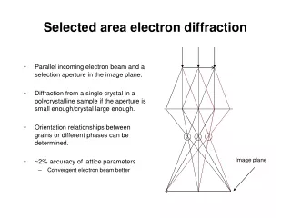
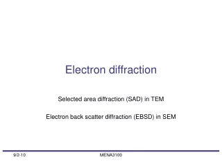
“standard EBSD set up” phosphor screen schematic view e- sample Perfect for practical applications! Limited use for understanding questions like: -Is the level of contrast of the pattern in agreement with theory? -What is the energy of the electrons that contribute to the contrast? -What is the depth of the sample that contributes to the contrast? -For compounds, do atoms at different sites generate the same contrast?
Our focus: Electron spectroscopy using high-energy (up to 40 keV) electrons. Hemispherical analyser 0.5 eV resolution slit lens Measure simultaneously quantitatively intensity along a line with good energy resolution. We use single crystals and a 0.3mm diameter beam
case 1: contrastSilicon (022) plane Greyscale image: calculated using the dynamical theory of diffraction (Winkelmann). We measure in between the yellow arrows.
spectrum of Si for two different outgoing directions (incoming beam along surface normal) (on average) increasing depth contrast no contrast
Contrast always maximum for zero energy loss? No! Energy loss is determined by length of incoming and outgoing path Outgoing path has to be long enough to build up diffraction pattern. Energy loss along incoming path does not affect contrast, energy loss along outgoing path does! Glancing in: incoming trajectory much longer than outgoing trajectory. For zero energy loss outgoing trajectory too short to build up contrast.
What is the recoil effect?: small ball (e.g. electron mass m) hits very large ball (e.g. nucleus mass M) (m << M) Momentum p0 Energy p02/2m Momentum 0 After collision (for scattering over 180° momentum transfer q » 2p0) Momentum »-p0 Energy p02/2m- q2/2M Momentum = q Energy q2/2M
This can be used to detect (large amounts of) hydrogen elastic peaks C polymer film scattering angle 45 degree Difference in elastic peak width is due to momentum of the scattering atoms (Doppler broadening) H C H C H
For larger scattering angles we can separate even heavier elements spectra of sapphire with some Au impurities at the surface. Cross section proportional to Z2 . Changing the crystal orientation appears to change the relative intensity. Here the Al intensity is enhanced in orientation “b”
A comparison of the Al and O Kikuchi band for different orientations Why the difference?
calculated patterns Al2O3 total Al2O3Al only Al2O3O only similar behaviour totally different behaviour
Easiest understood using the reciprocity principle (due to time reversal symmetry): diffraction along an outgoing direction affects the experiment in the same way as diffraction of an incoming beam along that direction would. Near diffraction conditions standing waves forms in the crystal. For some diffracting plane, the standing waves cause preferential interaction with either O or Al, in other cases no such preferential interaction occurs.
Answers to our question -Is the level of contrast of the pattern in agreement with theory? quite good: Ultramicroscopy Vol. 109 , pp. 1211 2009 -What is the energy of the electrons that contribute to the contrast? -What is the depth of the sample that contributes to the contrast? These are 2 related questions. Answer depends on geometry. New Journal of Physics Vol. 12 , pp. 053001 2010 -For compounds, do atoms at different sites generate the same contrast? Yes, when the crystal structure is favourable. (Physical Review Letters, in press) Thanks for your attention!