Download

1 / 17
170 likes | 339 Views
Waveguide group velocity determination by spectral interference measurements in NSOM. Bill Brocklesby Optoelectronics Research Centre University of Southampton, UK. Motivation/background. NSOM valuable for spatial measurements of propagation

E N D
Waveguide group velocity determination by spectral interference measurements in NSOM Bill Brocklesby Optoelectronics Research Centre University of Southampton, UK
Motivation/background • NSOM valuable for spatial measurements of propagation • Fs pulses give easily-resolvable spectral information about their propagation • Can measure evolution of continuum generation (Paper QFE5, Fri 11:30am, 203 B) • Spectral interference between two pulses separated by small time interval • NSOM can pick out this info with high spatial resolution
Spectral interference • Overlap of frequencies from each pulse with different phases causes interference • Results in spectral ‘fringes’ which vary with pulse separation • Well-known from coherent control experiments Pulse intensity vs time Pulse spectrum
Spectral interference • Overlap of frequencies from each pulse with different phases causes interference • Results in spectral ‘fringes’ which vary with pulse separation • Well-known from coherent control experiments Pulse intensity vs time Pulse spectrum
Spectral interference • Overlap of frequencies from each pulse with different phases causes interference • Results in spectral ‘fringes’ which vary with pulse separation • Well-known from coherent control experiments Pulse intensity vs time Pulse spectrum
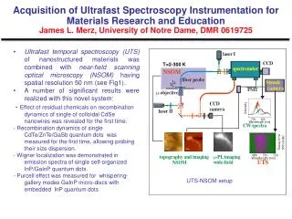
Ta2O5 waveguides designed for supercontinuum generation (Mesophotonics, Ltd) Set of rib guides on SiO2, all on Si wafer Ta2O5 has high n2 Can produce octave continuum with high-energy input pulses Typically multimode at 4m width Samples - Ta2O5 rib waveguides Ta2O5 guides 500nm 4m SiO2 Si wafer
100nm NSOM geometry SNOM probe • NSOM probe locked to surface via shear force • Uncoated probe samples evanescent field above guide • evanescent decay lengths different for each mode • Probe output to CCD-based spectrometer y x Continuum out 6mm uncoated pulled fiber tip, ~80nm tip diameter Femtosecond laser pulses in (87fs, 70MHz, 0.8nJ/pulse)
Spectrally-resolved NSOM data 90fs pulse, 800pJ • One lateral position along guide • Spectral fringes are clear in NSOM data • Some spectral broadening via SPM • high n2 guides • Red traces are not NSOM sampled - no interference guide output input laser
Transforming the spectral fringes • This is FT of spectral data - NOT the time profile • Same for constant spectral phase • Spectral fringes produce peaks in time data • Separation of peaks increases with time • Group velocity differences • Many different mode differences
Distance along guide Distance across guide NSOM and mode beating • Single frequency propagating along the guide in two modes will interfere, producing mode beating. • Example - TM00, TM01 lateral intensity profile with distance • Beat length given by phase velocity difference • NSOM tip on guide edge sees coupled intensity modulation
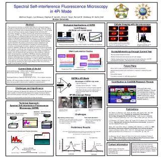
Local spectral fringe variation Simulation of spectral intensity variation • For each frequency, mode beating produces regular intensity modulation in NSOM signal along guide • Variation in phase velocity with wavelength causes spectral fringes at any particular length • Variation of spectral fringe separation with distance gives group velocity NSOM measurement of spectral intensity variation
Extracting group velocity information • Plotting peaks from previous graph • Different gradients give difference in group velocity between modes • Expressed in terms of group index (c/vg), we get ng between 0.058 and 0.258 ng= 0.1 ng= 0.058 ng= 0.174 ng= 0.258
Effect of nonlinearity 2.1nJ • Pulse energy varied from 0.8nJ to 2.1nJ • No deviation of mode spacing in time • Spectral broadening increases by x2 with pulse power 1.5nJ 0.8nJ 2.1nJ 1.5nJ 0.8nJ
Sensitivity to waveguide coupling Mode disappears Mode appears • Change input coupling • Change position of coupling lens • change mode distribution • Time pattern is sensitive to this • Particular differences appear and disappear from time profile Moving coupling lens lower
TM00 TM01 Mode calculation • Mode calculation • finite difference and effective index modeling • ~20 modes supported • Ta2O5 index varied with wavelength appropriately to get group velocities • Uncertainties in Ta2O5 index - annealing issues • Measured index is qualitatively correct • Too many modes to assign confidently calculated index differences
Summary • Spectral interference changes spectrum sampled by NSOM probe from multimode waveguide • Much information available • Differences in mode group velocities directly measured • Phase velocity at each wavelength also available in principle - check on group velocity. • GVD via peak width? • Plans to repeat with smaller, better characterized guides • Fewer modes = more tractable • Well-defined index makes accurate mode calculation possible
Acknowlegements John D. Mills, Tipsuda Chaipiboonwong Optoelectronics Research Centre, University of Southampton, SO17 1BJ, UK Jeremy J. Baumberg3,4 [4] Dept of Physics and Astronomy, University Of Southampton, SO17 1BJ, UK Martin D.B. Charlton2,3, Caterina Netti3, Majd E. Zoorob3, [2] School of Electronics and Computer Science, University of Southampton, SO17 1BJ, UK [3] Mesophotonics Ltd, Southampton Science Park, Southampton, SO16 7NP, UK