Download
1 / 15
150 likes | 384 Views
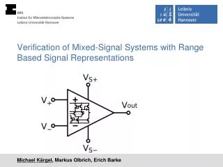
Verification of Mixed-Signal Systems with Range Based Signal Representations. Michael Kärgel , Markus Olbrich, Erich Barke. Contents. Motivation Mixed-Signal Simulation Affine Arithmetic Analog Circuit Simulation using Affine Arithmetic Delay Modeling SystemC Integration Results

E N D
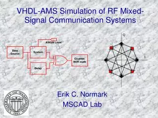
Verification of Mixed-Signal Systems with Range Based Signal Representations Michael Kärgel, Markus Olbrich, Erich Barke
Contents • Motivation • Mixed-Signal Simulation • Affine Arithmetic • Analog Circuit Simulation using Affine Arithmetic • Delay Modeling • SystemC Integration • Results • Conclusion Michael Kärgel, Markus Olbrich, Erich Barke, FAC2013, 14.02.2013
Verification of Mixed-Signal Systems • Problems • Slow • Rarely used • Fast enough only on system-level • Too abstract for analog systems • Missing variation due to degradation or manufacturing • Gain • Find design errors • Is every error really critical for the function of a system? • Reduce overdesign of modules • Smaller design Michael Kärgel, Markus Olbrich, Erich Barke, FAC2013, 14.02.2013
Mixed-Signal Systems: Parameter Variations Michael Kärgel, Markus Olbrich, Erich Barke, FAC2013, 14.02.2013
Affine Forms • Mathematical model for error tracking • Origin in numerical applications, first used by Stolfi et al. • Guaranteed save inclusion of the result • One unique symbol for each parameter deviation • Exact affine operations • Linear operations: +,− • Multiplication with constant Linear partial deviations Deviationsymbol Central value Michael Kärgel, Markus Olbrich, Erich Barke, FAC2013, 14.02.2013
Non-affine Operations • Approximations of the result of each operation • Linear correlation preserved • One new deviation generated for each operation • Guaranteed safe inclusion • Conversion to interval arithmeticusing radius-function • C++-Library licensed under GPL • http://aaflib.sourceforge.net/ Michael Kärgel, Markus Olbrich, Erich Barke, FAC2013, 14.02.2013
Affine Circuit Simulation • DC/AC/Transient simulation methods implemented • SPICE-like approach • Newton-Raphson based solving • Include all deviation in a single simulation run • Speed up verification • Tracing of deviationsfrom output back toinputs and parameter Affine Monte- Carlo Corner- Case Michael Kärgel, Markus Olbrich, Erich Barke, FAC2013, 14.02.2013
Delay Modeling in Digital Circuits (I) Michael Kärgel, Markus Olbrich, Erich Barke, FAC2013, 14.02.2013
Delay Modeling in Digital Circuits (II) • Delay models consider • Signal variations (Slew rate) • Process parameter variations (Capacitance, ...) • Delay models do not represent • Permanent bit errors • Logic value errors on system level • Delay values • Fast and slow corners (inter die variation) • SSTA (intra die variation) • Stored in device library Michael Kärgel, Markus Olbrich, Erich Barke, FAC2013, 14.02.2013
Conversion between Affine and Delay Signals Michael Kärgel, Markus Olbrich, Erich Barke, FAC2013, 14.02.2013
Event DrivenSystemCInterface • Analog simulator using affine arithmetic • Integration of events between SystemC and the simulator • Reduce interpolation errors • Analog sampling as fallback solution Simulation kernel(C++) Event system DE-MOC Analog sampling Michael Kärgel, Markus Olbrich, Erich Barke, FAC2013, 14.02.2013
Example: SystemC PWM brightness control analog Testbench PWM clock enable brightness Michael Kärgel, Markus Olbrich, Erich Barke, FAC2013, 14.02.2013
Example: 3 Bit Flash ADC • Reference voltage + resistor ladder • Deviation in OPA parameters as well as in reference • Digital models with delays • Functional modeling Michael Kärgel, Markus Olbrich, Erich Barke, FAC2013, 14.02.2013
Future Work • Preserve correlation in both domains • Requires transformation between values and time of deviation symbols and delays • Enables more complex examples, e.g. Sigma Delta Converter • Special comparator models or converter units • Modeling of memories and registers • Modeling of functionality changing errors Michael Kärgel, Markus Olbrich, Erich Barke, FAC2013, 14.02.2013
Conclusion • Modeling of variation effects in mixed signal circuits • Affine arithmetic • Analog circuit simulation using affine arithmetic • Delay model for digital circuits • Mixed signal simulation with variation Michael Kärgel, Markus Olbrich, Erich Barke, FAC2013, 14.02.2013