Download
1 / 73
790 likes | 2.44k Views
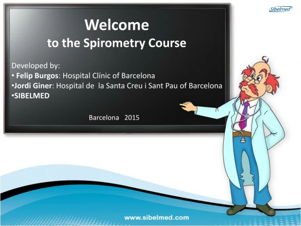
Welcome to the Spirometry Course developed by Felip Burgos and Jordi Giner from Barcelona. Learn about the history, types, and requirements of spirometers. Understand the significance of spirometry in studying lung function and respiratory disorders like asthma and COPD. Explore various types of spirometers and their characteristics.

E N D
Welcome to the Spirometry Course • Developed by: • Felip Burgos: Hospital Clínic of Barcelona • Jordi Giner: Hospital de la Santa Creu i Sant Pau of Barcelona • SIBELMED Barcelona 2015
SpirometryHistory Let's Begin
History of Spirometry Let's Begin Etymologically, spirometry means the measurement of breath or breathing. The term is attributed to Lavoisier (1862), who discovered oxygen and gave it its name.
First Attempt to Measure Lung Capacity Galen (AD 129-200) Doctor and Greek philosopher In his experiment, he asked a child to breath into a bladder, observing that the volume entering the bladder did not vary with eachbreath.(he did not record any measurements).
The First Spirometer John Hutchinson (1811-1861) Inventor of the spirometer. He made more than 4000 spirometers • Born in Newcastle • He studied medicine at the University of London and surgery at Southampton. • He worked for 2 years at London Brompton Hospital, where he developed his spirometry working theories and principles (1846). • As we know it today, spirometry was developed by him when designing the spirometer model.
John Hutchinson (1811-1861) Lineal relation between VC and height vc He observed that the volume of air that could be exhaled from the lungs when completely inflated (Vital Capacity or VC) was a good indicator of an individual's longevity. When this measure was compromised, premature death was expected. (PROGNOSIS VALUE).
Other Early Spirometers Spirometer made in 1850 (Pixxi Family, Paris 1850) and by Dr. S.W. Mitchell (1859). Portable Spirometers (Circa 1900). Water Spirometer (Godart, 1960)
First Spirometry Performed at Hospital de la Santa Creu i Sant Pau. (Barcelona 1958) Unknown Author / Fons Escuela Claret
Ventilation Diagram 8 6 4 VC 2 TLC I RV vt 0 E RV FRC RV VC: Vital Capacity Vt: Tidal Volume RV: Residual Volume ERV: Expiratory Reserve Volume TLC: Total Lung Capacity FRC: Functional Residual Capacity IRV: Inspiratory Reserve Volume
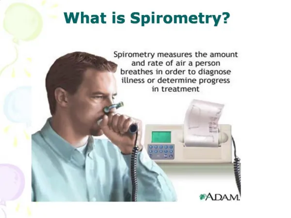
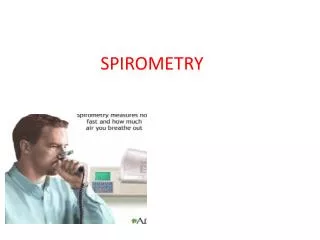
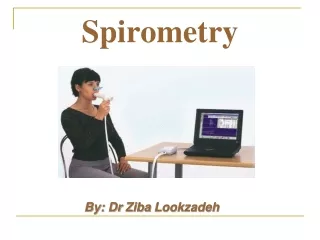
What is Spirometry? • Spirometry is a test which is essential to study lung function. It measures the volume of air moved during a maximum and forced exhale. • It is useful for studying respiratory problems (asthma, COPD, etc.) and to evaluate possible occupational pulmonary disorders.
Spirometry 8 VEMS = FEV1 6 FVC 4 In the 1st second 2 0 VEMS:VolumeExpiratoireMaximumSeconde(MaximumExpiratory Volumein one Second) FEV1:Forced Expiratory Volumein the first Second
COPD ChronicObstructive Pulmonary Disease is characterized by a chronic and irreversible obstruction of the airflow caused, mainly, by an inflammatory reaction to tobacco smoke. (GOLD; GESEPOC) ASTHMA Chronic respiratory disease characterized by the inflammation of the airways, hyperresponsive to a wide variety of stimuli and reversible bronchial obstruction. (GINA; GEMA) Flow (L/s) Volume (L)
Types of Spirometer • According to their properties • Water / Dry • Closed / Open • Volumetric / Pneumotachometer • According to their use • Pulmonary function laboratories • Patient screening • The most used are Pneumotachometers(Open) • Types of Pneumotachometer: • Lilly • Fleisch • Turbine • Ultrasonic • Venturi • Other: Hot wire, Pitot, etc.... • Characteristics (pneumotachometers) • They are the open type • They are flow sensors • Flow-time relation • Calculate volumes by microprocessor • Different types of curves: • Volume/Time • Flow/Volume Tachometer: From the Greek τάχος, tachos, ‘velocity’ and μέτρον, metron, ‘measure’ (In some bibliographies the pneumotachometer is referred to as pneumotachograph)
Spirometer Requirements • Measure a minimum volume of 8 liters and a flow of 0 to 14 l/s • Measure a volume with a minimum precision of ± 3% or ± 50ml (whichever is better) • Signal accumulation during 30" • Resistance to a 14 l/s flow less than 1.5 cmH2O • Assessment of the start of the maneuver by retrograde extrapolation • Simultaneous graph-plotting
Water Bell Spirometer Water Spirometer Moves the paper and marker Thebellmoveswhenexhaling Results are plotted
Bellows Spirometer Closed and Dry Type Moves the paper and marker Theresultsappear • Registers the forced expiration. • The most used spirometer until the pneumotachometer. When exhaling the bellows inflate
Piston Spirometer Closed and Dry Type Moves the paper, and plots results When exhaling, the piston and marker move • Sealed cylinder prevents air escaping.
LILLY Pneumotachometer (operating principle) Measurement based on the difference in air-flow pressure before and after passing through a known RESISTANCE (screen (A)), which is directly proportional to the airflow that passes through a PRESSURE SENSOR. Once the flow is obtained, the microprocessor calculates the volumes by mathematically integrating the flow with the time function. Pneumotachometerdiagram LILLY A P1 P2 B Disposable Lilly Pneumotachometer Avoids cross contamination A: Resistance B:Pressure sensor or differential transducer The differential transducer measures the pressure before the resistance (P1) and after the resistance (P2) to calculate the flow; using integration of the flow the volume is obtained.
FLEISCH Pneumotachometer (operating principle) Measurement based on the difference in airflow pressure before and after passing through a known RESISTANCE (capillaries arranged in parallel(A)), which, is directly proportional to the flow of that passes through a PRESSURE SENSOR. Once the flow is obtained, the microprocessor calculates the volumes by mathematically integrating the flow with the time function. Pneumotachometer diagram FLEISCH A P1 P2 B A: Resistance B:Pressure sensor or differential transducer The differential transducer measures the pressure before the resistance (P1) and after the resistance (P2) to calculate the flow; using integration of the flow the volume is obtained.
ROTATION TURBINE (operating principle) The TURBINE spirometer acquires physical signals and processes the information that the signal provides in relation to the pulmonary function. During the process, physical energy is converted into electrical energy. The units that produce this change are called transducers. TRANSMITTER RECEIVER • The transduction function is performed in two stages: • The volume to be measured passes through the turbine and causes the rotor to turn proportionally. • The turn is detected by a break in an infrared light beam, whose sensor converts the light received into a digital electrical signal.
Ultrasonic (operating principles) To calculate the flow, these transducers use the ultrasonic wave property: when they form a certain angle with respect to the flow direction, ultrasonic waves that travel in the same direction as the flow take less time to arrive to the receiver than those traveling in the opposite direction. A C B
Spirometry Volume (L) Flow (L/s) Time (s) Volume (L)
Contribution of both graphs Check for correctend Check the quality of the maneuver Flow (L/s) Volume (L) Ensure that the start was sudden and without hesitation Ensure that the start was sudden and without hesitation Time (s) Volume (L)
Functional Alterations: • Obstruction • No Obstruction
Lungs Lung of a healthyperson Lung of the same person with COPD Bronchus Normal airway Airway in asthma Airway in COPD Contracted smooth muscle Muscle smooth still relaxed Relaxed smooth muscle Air trapped in the alveolus Inflamedwall Inflamed and swollen wall
Spirometry “Normal” Airway Flow (L/s) Volume (L) Time (s) Volume (L)
Spirometry Obstructed Airway Flow (L/s) Volume (L) Time (s) Volume (L)
Spirometry NON-Obstructive Airway Flow (L/s) Volume (L) Time (s) Volume (L)
Spirometry Mixed Airway Flow (L/s) Volume (L) Time (s) Volume (L)
Spirometric Parameters FVC : Forced Vital Capacity (FVC) Volume of air expelled during a forced expiration maneuver (L). FEV1: Forced Expiratory Volume in the first second. FEV1/FVC : Expresses the volume of air expelled in the first second with respect to the maximum that can be expelled during the forced expiration maneuver. FEV6: Forced Expiratory Volume in the sixth second (L). Forced Spirometry FVC FEV1 FEV6 Volume (L) Time (s)
Spirometric Parameters • PEF (PeakFlow) • Maximum expiratory flow or peak flow. • Maximum flow achieved during the forced expiration maneuver. • It is generated before having expelled 15% of the FVC and must be maintained for a minimum of 10 ms (milliseconds) • Expressed in L/sec. • Effort-dependent parameter. Forced Spirometry PEF Flow (L/s) Volume (L)
Spirometric Parameters FEF 75 FEF 50 % Maximum flowwhenthe 50% of the FVC has beenexhaled. FEF 25-75 % Maximum flow between 25% and 75% of the FVC (mid-expiratory flows). Mid-expiratory flows may early detect obstruction (in the small tract), but they are highly variable. FEF 50 Forced Spirometry FEF 25 FEF Flow (L/s) Volume (L)
Spirometry Obstructed Airway FVC ≈ FEV6 FEV1 FEV1 FVC Inflamed and swollen wall FEV6 1 sec Volume (L) 6 sec Time (s)
FVC ≈ FEV6 6 sec In patients with an obstruction in the airflow, the expiratory maneuver can be tedious and prolonged, have insufficient relevance and wide variability; therefore, specific authors and consensus suggest that, in these cases, the value of FEV6 (forced expiratory volume in the sixth second) is comparable to the FVC. Likewise, the ratio FEV1/FVC would be replaced by FEV1/FEV6.
Whichparametersshouldwefocuson? On the screen we can see selected some of the 'most significant' parameters. The other parameters, although important, have less relevance.
“Normal” Spirometry > 80% reference value PEF Between 70% and 80% Curve Flow / Volume Curve Volume / Time FEV1 3.9 (L) FVC5.0 (L) FEV1/ FVC78% FVC FVC FEV1 Flow (L/s) Volume (L) Time (s) Volume (L)
“Obstructive” Spirometry PEF Less than 70% Curve Flow / Volume Curve Volume / Time FVC FVC FEV1 1.5 (L) FVC4.0 (L) FEV1/ FVC38% FEV1 Flow (L/s) Volume (L) Volume (L) Time (s)
Spirometry Progression of the Obstruction COPD ChronicObstructive Pulmonary Disease is characterized by a chronic and irreversible obstruction of the airflow caused, mainly, by an inflammatory reaction to tobacco smoke (GOLD, GESEPOC). COPD Flow (L/s) Volume (L)
“NON-Obstructive” Spirometry PEF Greater than 80% Curve Flow / Volume Curve Volume / Time FVC FEV1 1.8 (L) FVC1.9 (L) FEV1/ FVC95% FVC FEV1 Flow (L/s) Volume (L) Time (s) Volume (L)
Reference Values (Also denoted THEORETICAL)
Reference Values (theoretical) Objective: Compare the measured values with the corresponding values of Sex, Age, Size, Weight and Ethnicity. Material (reference equations): FVC: M 0.028 T + 0.0345 P + 0.0573 E - 3.21 F 0.0305 T + 0.0356 P + 0.0356 E - 3.04 ANTHROPOMETRY Method: The observed / reference values expressedas a %.
Reference Values (theoretical) Recommended spirometric reference values in our environment