Download
1 / 17
170 likes | 308 Views
Architecture-driven Modeling and Analysis. By David Garlan and Bradley Schmerl Presented by Charita Feldman. Deficiencies of Architectural Design Specifications. Common practices in representing software architecture luck an ability to:

E N D
Architecture-driven Modeling and Analysis By David Garlan and Bradley Schmerl Presented by Charita Feldman
Deficiencies of Architectural Design Specifications Common practices in representing software architecture luck an ability to: • Express architectural descriptions precisely and unambiguously • Establish criteria for soundness and consistency of architectural designs • Analyze designs to determine implied properties • Apply and enforce design patterns • Guarantee that system implementation is consistent with its architectural design
Modeling Architectural Structures • There are three distinctive views that describe architectural design, each exposing certain aspect of the system: • Coding structures views (modules, packages, classes and relationships between them) • Run-time structures or component and connector views (databases, clients, servers, and connectors indicating communication ways) • Allocation structures views (deployment and work break down structures)
Elements of Components and Connectors view • Components model principal run-time elements that have a set of ports • Ports model component’s interfaces through which component interacts with other components via connectors • Connectors model the pathways of communication between components and have a set of roles • Roles model the specifications of behavior requires of the components that use a given connector
Example of Component and Connector (C&C) Model in Acme ADL • Simple-cs system consist of a single client and a single server, interacting through rpc based connector • In this representation we can analyze our C&C model to see if there are any unattached roles or ports, name collisions and etc.
Modeling Architectural Properties in Acme ADL • Properties are name-value pairs that can be associated with any architectural element: component, port, connector • Sync-request port property indicates if rpc-request port is synchronous or asynchronous, max-transactions-per-second and max-clients-supported component properties indicate maximum properties of server component and protocol property of rpc connector indicates the name of the communication protocol
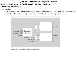
Example of Modeling Architectural Properties in Acme Studio • Clients queue request for database through set of servers • Using arrival rate, average service time and degree of server replication properties analysis tool calculates average service utilization, queue length and response time. It determined that one of the servers is overloaded
Modeling Architectural Behavior • Which is reading and writing end of the pipe? • Is writing syncronous? • What if F2 tries to read and the pipe is empty? Does it wait for input? • Can F1 choose to stop writing? • Can F2 choose to stop reading? • Can F1 close and reopen the pipe? • Can F1 write indefinetey if F2 never reads from pipe?
Modeling Architectural Behavior in Wright specification language • Events model architecturally relevant actions • Processes represent patterns of events • Sequences represent the ability to follow one behavior by another • Choices model branching • Composition model partial description
Modeling Architectural Behavior in Wright specification language (cont.) • Wright specifications of architectural behavior can be associated with various architectural structures, including ports and roles From the model we can see that • Writer pipe can close at any time and cannot reopen • Reader can close at any time • No deadlocks in glue specifications • Component interface of filters F1 and F2 or ports satisfy the requirements of connector’s roles
Modeling Architectural Styles • Some systems share a common architectural design vocabulary and a set of constraints on that vocabulary (for example, “client-server systems”, “pipe-filter systems” and etc. is vocabulary, “clients cannot talk directly to other clients” is constrain) • Architectural styles can specified in Acme ADL by defining components, connectors, properties and defining constraints on how instances of components, connectors and properties can be combined in a system description.
Family represents architectural style Invariant represents constraints – data type written to a pipe must match the data read from it Systems can be defined as an instance of the style, components and connectors may de declared as instances of the types defined in family. Modeling Architectural Styles in Acme ADL
Mapping between Architecture and Implementation • There are two methods of insuring that the implementation system is consistent with intended architecture: • Construction – concrete model is constructed by applying well-defined refinement rules to an abstract model. This method can be completely automated – called generation • Comparison – of the concrete model and abstract model by providing mapping relationships between the two models
Mapping between Architecture and Implementation by Construction • Applying well defined refinement rules to a more abstract model can be difficult • Can be simplified by using architectural styles – limiting the problem to a specific class system and a specific class of implementations. This way it’s possible to automate the process and generate code
Mapping between Architecture and Implementation by Comparison • There are two approaches to compare implementation and architecture: • Static analysis – infer architecture by analyzing the code. This approach is effective for inferring module-oriented structures • Dynamic analysis – capture run-time behavior of the system and relate it architectural models. This approach is effective when inferring run-time structure such as C&C models.
Related Work • ADLs and associated toolsets focus mostly on component and connector structures and their properties (UML 2.0) • Specification and analysis of architectural behaviors that are mostly focused on finding mismatches in component compositions (Wright, Chemical Abstract Machine, PO-Sets, Category Theory, Pi Calculus, Statecharts) • Refinement and generation to map architectures and implementations (UniCon, ArchJava, MDA)
Conclusion • A little formality goes a long way • Simple structures with types, properties, relations and behavioral descriptions can help provide a clear and unambiguous architecture • Reuse of existing methods • Most of the formal modeling can be done using existing tools, simulators and model generators • One size does not fit all • The more general-purpose a model, the fewer opportunities for deep analysis • Areas for improvement • Dynamic Architectures – modeling architectural structures that change dynamically • SA for Emerging Systems – modeling for different computational units, adaptive components • Managing Multiple Views – most of the tools focus on component and connector views, need to manage relationships between different views