
System Software
E N D
Presentation Transcript
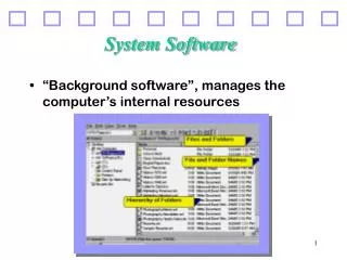
System software- A system software is a collection of system programs that perform a variety of functions i.e file editing, resource accounting, IO management, storage management etc. • System program – A system program (SP) is a program which aids in effective execution of a general user’s computational requirements on a computer system. The term execution here includes all activities concerned with the initial input of the program text and various stages of its processing by computer system, namely, editing, storage, translation, relocation, linking and eventual execution. • System programming- System programming is the activity of designing and implementing SPs. • The system programs of a system comprises of various translators (for translating the HLLs to machine language) .The machine language programs generated by various translators are handed over to operating system (for scheduling the work to be done by the CPU from moment to moment). Collection of such SPs is the system software of a particular computer system
Introduction to Software Processors A contemporary programmer very rarely programs in the one language that a computer can really understand by itself---the so called machine language. Instead the programmer prefers to write their program in one of the higher level languages (HLLs). This considerably simplifies various aspects of program development, viz. program design, coding, testing and debugging. However, since the computer does not understand any language other than its own machine language, it becomes necessary to process a program written by a programmer so as to make it understandable to the computer. This processing is generally performed by another program, hence the term software processors. Broadly the various software processors are classified as: - Translators - Loaders - Interpreters
Program 1 Software processor 1 Program 2 Software processor II The software processor 1 in the figure is known as a translator. It performs the task of converting a program written in one language (HLL program termed as program 1) into a program written in another programming language (program 2). Software processor II is called a loader also known as linkage editor. The loader performs some very low- level processing of program 2 in order to convert it into a ready –to-run program in the machine language (program 3). This is the program form which actually runs on the computer , reading input data, if any, and producing the results. Other programs Results Program 3 ComputerSystem
Translators of programming languages are broadly classified into two groups depending on the nature of source language accepted by them. • An assembler is a translator for an assembly language program of a computer. An assembly language is a low-level programming language which is peculiar to a certain computer or a certain family of computers. • A compiler is a translator for a machine independent High Level language like FORTRAN, COBOL, PASCAL. Unlike assembly language, HLLs create their own feature architecture which may be quite different from the architecture of the machine on which the program is to be executed. The tasks performed by a compiler are therefore necessarily more complex than those performed by an assembler. The output program form constructed by the translator is known as the object program or the target program form. This is a program in a low-level language---possibly in the machine language of the computer. Thus the loader, while creating a ready-to-run machine language program out of such program forms, does not have to perform any real translation tasks. The loader’s task is more in the nature of modifying or updating the parts of an object program and integrating it with other object programs to produce a ready –to-run machine language form
Interpreter- Another software processor is an interpreter. The interpreter does not perform any translation of the source program. Instead, it analyzes the source program statement by statement and itself carries out the actions implied by each statement. An interpreter, which is itself a program running on the computer, in effect simulates a computer whose machine language is the programming language in which the source program is written SoftwareProcessor Program 1 Results ComputerSystem Data Execution of HLL program using an interpreter
Elements of Assembly language Programming- An assembly language program is the lowest level programming language for a computer. It is peculiar to a certain computer system and is hence machine-dependent. When compared to a machine language, it provides three basic features which make programming a lot easier than in the machine language • Mnemonic operation Code- Instead of using numeric operation codes (opcodes), mnemonics are used. Apart from providing a minor convenience in program writing, this feature also supports indication of coding errors,i.e misspelt operation codes. • Symbolic operand specification- Symbolic names can be associated with data or instructions. This provides considerable convenience during program modification. • Declaration of data/storage areas- Data can be declared using the decimal notation. This avoids manual conversion of constants into their internal machine representation.
An assembly language statement has the following general format [Label] Mnemonic OP Code Operand [Operand…] • Types of statements in an assembly language program: • Imperative statement- An imperative assembly language statement indicates action to be performed during execution of assembly program. Hence each imperative statement translates into( generally one) machine instruction The format of machine instruction generated has the format sign opcode index register operand address • Declarative statements- A declarative assembly language statement declares constants or storage areas in a program. For example the statement A DS 1 indicates that a storage area namely A is reserved for 1 word. G DS 200 indicates that a storage area namely G is reserved for a block of 200 words.
Constants are declared using statement ONE DC ‘1’ indicating that one is the symbolic name of the constant 1. Many assemblers permit the use of literals. These are essentially constants directly used in an operand field ADD ‘=1’ = preceding the value 1 indicates that it is a literal. The value of the constant is written in the same way as it would be written in a DC statement. Use of literals save the trouble of defining the constant through a DC statement and naming it. • Assembler Directives- Statements of this kind neither represent the machine instruction to be included in the object program nor indicate the allocation of storage for constants or program variables. These statements direct the assembler to take certain actions during the process of assembling a program. They are used to indicate certain things regarding how assembly of the input program is to be performed. For example START 100 indicating that first word of the object program to be generated by the assembler should be placed in the machine location with address 100
Similarly, the statement END indicates that no more assembly language statements remain to be processed.
AN ASSEMBLY PROCESS • The overall process of conversion of an assembly language program to its equivalent machine code can be broadly divided into two phases: • Analysis phase • Synthesis phase Analysis Synthesis Translation from of + of = Source to Target Source text Target Text Text
Analysis Phase- This phase is mainly concerned with the understanding of syntax (rules of grammar) and semantics (rules of meaning) of the language. The various tasks that have to be performed during this phase are: • Isolate the label, mnemonic operation code and operand fields of a statement • Enter the symbol found in label field (if any) and address of the next available machine word into the symbol table • Validate the mnemonic operation code by looking it up in the Mnemonic table • Determine the storage requirements of the statement by considering the mnemonic operation code and operand fields of the statement. Calculate the address of the first machine word following the target code generated for this statement (Location counter processing)
Synthesis Phase- The basic task of the synthesis phase is to construct the machine instruction for the corresponding assembly language code. In this phase we select the appropriate machine operation code for the mnemonic and place it in the machine instruction’s operation code field. Operand symbols are replaced by their corresponding addresses. The symbols and their addresses are maintained in the analysis phase in the form of symbol tables. The various tasks that are performed during synthesis phase are: • Obtain the machine operation code corresponding to the mnemonic operation code by searching the Mnemonic table • Obtain the address of the operand from the symbol table. • Synthesise the machine instruction or the machine form of the constant, as the case may be.
Location counter processing- The best way to keep track of the addresses to be assigned is by actually using a counter called the location counter. By convention, this counter always contain the address of the next available word in the target program. At the start of the processing by the assembler, the default value of the start address (by convention generally the address 0000) can be put into this counter. When the start statement is processed by the assembler, the value indicated in its operand field can be copied into the counter. Thus, the first generated machine word would get the desired address. Thereafter whenever a statement is processed the number of machine words required for by it would be added to to this counter so that it always points to the next available address in the target program.
A simple Assembly Scheme- Fig: 1 Let us start applying the translation model to the assembly scheme given. As the END statement in the scheme is with a label, the execution of the program starts from the statement that bears the label First. As regards the analysis of the an assembly statement say, FIRST READ A All the information required to design the analysis phase is given. We already know the three fields: label, opcode mnemonic and operand field. The mnemonic opcode is checked whether it is valid or not by comparing it with the list of mnemonics of the language provided. Once, the mnemonic turns out to be valid, we determine whether the symbols written followed the symbol writing rules. This completes the analysis phase.
In the synthesis phase, we determine the machine operation code for the mnemonic used in the statement. This can be achieved by maintaining the list of machine opcode and corresponding mnemonic opcode. Net we take the symbol and obtain its address from the symbol table entry done during the analysis phase. This address can be put in operand address field of the machine instruction to give it the final form.
Pass Structure of an assembler-In order to understand the pass structure of an assembler, we need to first understand its need and significance. This can be understood with the help of an assembly program. The assembly scheme given in fig 1, when input to an assembler, is processed in the following way. Processing of the START statement will lead to initialization of the location counter to the value 100. On encountering the next statement A DS ‘1’ the analysis phase will enter the (symbol, address) pair (A,100) into the symbol table. Location counter will be simply copied into the appropriate symbol table entry. The analysis phase will then find that DS is not the mnemonic of a machine instruction, instead it is a declarative. On processing the operand field, it will find that one storage location is to be reserved against the name A. Therefore LC will be incremented by 1. On processing the next two statements, the (symbol, address) pairs (B,101) and (FIRST,102) will be reentered into the symbol table. After this the following instructions will be generated and inserted into the target program
Address Instruction opcode operand Address 102 09 100 103 09 101 104 04 100 105 02 101 generation of these instructions is quite straightforward since the opcodes can be picked up from the mnemonics table and the operand addresses from the symbol table. The next statement to be processed is: TRIM LARGEG While synthesizing the machine instruction for this statement, the mnemonic TRIM would be translated into machine operation code ’07’. While processing the operand field, the assembler looks for LARGEB in the symbol table. However this symbol is not present there. On looking at the source program again, we find that the symbol LARGEB does appear in the label field of third-last assembly statement in the program
The problem arising in processing this reference to symbol LARGEB belongs to assembler rather than the assembly program being translated. This problem arises as the definition of LARGEB occurs in the program after its reference. Such a reference is called forward reference . We can see that similar problems will arise for all the forward references. Thus we have to find a solution to this problem of assembling such forward references. • On further analysis of situation. We can see that this problem is not any shortcoming of our translation model but it is the result of our application of the translation model to an arbitrary piece of the source program, namely a statement of the assembly language. For the translation to succeed, we must select a meaningful unit of the source program which can be translated independent of subsequent units in it. In order to characterize the translation process on this basis, we introduce the concept of a translator pass, which is defined as: • A translator pass is one complete scan of the source program input to the translator, or its equivalent representation
Multipass Translation – Multipass translation of the assembly language program can take care of the problem of forward references. Most practical assemblers do process an assembly program in multiple passes. The unit of source program used for the purpose of translation is the entire program. • While analyzing the statements of this program for the first time, LC processing is performed and symbols defined in the program are entered into the symbol table. • During the second pass, statements are processed for the purpose of synthesizing the target form. Since all the defined symbols and their addresses can be found in the symbol table, no problems are faced in assembling the forward references. In each pass, it is necessary to process every statement of the program. If this processing is performed on the source form of the program, there would be a certain amount of duplication in the actions performed by each pass. In order to reduce this duplication of effort, the results of analyzing a source statement by the first pass are represented in an internal form of the source statement. This form is popularly known as the intermediate code of the source statement.
SymbolTable SourceProgram Target Program Pass II Pass I IntermediateCode Assembler
Single Pass Translation- Single pass translation also tackles the problem of forward references in its own way. Instructions containing forward references are left incomplete until the address of the referenced symbol becomes known. On encountering its definition, its address can be filled into theses instructions. Thus, instruction corresponding to the statement TRIM LARGEB the statement will only be partially synthesized. Only the operation code ’07’ will be assembled to reside in location 106. The need for putting in the operand address at a later stage can be indicated by putting in some information into a Table of Incomplete Instructions(TII). Typically, this would be a pair (106,LARGEB). At the end of the program assembly, all entries in this table can be processed to complete such instructions.
Single pass assemblers have the advantage that every source statement has to be processed only once. Assembly would thus proceed faster than in the case of multipass assemblers. However, there is a disadvantage. Since both the analysis and synthesis have to be done by the same pass, the assembler can become quite large.
Design of a two-pass assembler- The design of two pass assembler depends on the type of tasks that are done in two passes of assembler. The pass wise grouping of tasks in a two-pass assembler is: • Pass 1- • Separate the symbol, mnemonic opcode and operand fields • Determine the storage required for every assembly language statement and update the location counter • Build the symbol table • Construct intermediate code for every assembly language statement • Pass II • Synthesize the target code by processing the intermediate code generated during pass 1
Pass 1- In pass 1 of the assembler, the main task lies in maintenance of various tables used in the second pass of the translation. Pass 1 uses the following data structures for the purpose of assembly: • OPTAB: A table of mnemonic opcodes and certain related information • SYMTAB: The Symbol table • LITTAB: A table of literals used in the program • Functioning of pass 1 centers around the interpretation of entries in OPTAB. After label processing for every source statement, the mnemonic is isolated and searched in OPTAB. If it is not present in OPTAB, an error is indicated and no further processing needs to be done for the statement. If present, the second field in its (OPTAB) entry is examined to determine whether the mnemonic belongs to the class of imperative, declarative or assembler directive statements. In the case of an imperative statement, the length field contains the length of the corresponding machine instruction. This is simply added to the LC to complete the processing of this statement.
For both assembler directive and declarative statements, the ‘Routine id’ field contains the identifier of a routine which would perform the appropriate processing for the statement. This routine would process the operand field of the statement to determine the amount of storage required by this statement and update the LC appropriately. • Similarly for an assembler directive the called routine would perform appropriate actions before returning. In both these cases, the length field is irrelevant and hence ignored. • Each SYMTAB entry contains symbol and address fields. It also contains two additional fields ‘Length’ and ‘other information’ to cater for certain peculiarities of the assembly. • In the format of literal table LITTAB, each entry of the table consists of two fields, meant for storing the source form of a literal and the address assigned to it. In the first pass, it is only necessary to collect together all literals used in a program. For this purpose, on encountering a literal, it can be simply looked up in the table. If not found, a new entry can be used to store its source form. If a literal already exists in the table, it need not be entered a new. However possibility of multiple literal pools existing in a program forces us to use a slightly more complicated scheme. When we come across a literal in the assembly statement, we have to find out whether it already exists in current pool of literals. Therefore awareness of different literal pools has to be built into the LITTAB organization. The auxiliary table POOLTAB achieves this effect. This table contains pointers to the first literal of every pool. At any stage, the start of the current pool is indicated by the last of the active pointers in POOLTAB. This pool extends up to the last occupied entry of LITTAB.
Meanings of some other assembler directives • ORIGIN- The format of this directive is: ORIGIN address specification The address specification is any expression which evaluates to a value of type ‘address’. The directive indicates that the location counter should be set to the address given by the address specifications. • EQU- The EQU statement simply defines a new symbol and gives it the value indicated by its operand expression. • LTORG- A literal is merely a convenient way to define and use a constant. However, there is no machine instruction which can directly use or operate on a value. Thus while assembling a reference to a literal, the following responsibilities devolve on the assembler. • Allocation of a machine location to contain the value of literal during execution • Use of the address of this location as the operand address in the statement referencing the literal Locations for accommodating the literals cannot be determined arbitrarily by the assembler. One criteria for selecting the locations is that control should never reach any of them during execution of the program. Secondly they should be so allocated as not to interfere with the intended arrangement of program variables and instructions in the storage.
By convention, all literals are allocated immediately following the END statement. Alternatively, the programmer can use the LTORG statement to indicate the place in the program where the literals may be allocated. At every LTORG Statement, the assembler allocates all literals used in the program since the start of the program or since the last LTORG statement. Same action is done at the END statement. All references to literals in an assembly program are thus forward references by definition
Difference between passes and phases of an assembler Phases Passes • Phases of an assembler define Pass defines the part of total the overall process of translation translation task to be performed of an assembly language program to during one scan of the source machine language program. program or its equivalent • There are two phases of an There can be any number of Assembler----Analysis phase passes ranging from one to n And synthesis phase
INTERMEDIATE CODE FORMS Simultaneous with the processing of imperative, declarative and assembler directive statements, pass 1 of the assembler must also generate the intermediate code for the processed statements to avoid repetitive analysis of same source program statements. Variant forms of intermediate codes, specifically operand and address fields, arise in practice due to trade off between processing efficiency and memory economy. • Intermediate Code---variant 1 Features of this intermediate code form is given below: • The label field has no significance in intermediate code • The source form of mnemonic field is replaced by a code depending on the class of the statement. • For imperatives, this code is the machine language operation code itself. Class name can also be added with the opcode. The class name for imperatives is IS. For example the mnemonic Read will be represented as 09 or (IS,09)-------(statement class, code) • For declarative and assembler directives, this code is a flag indicating the class and a numeric identifying the ordinal number within the class. The class names for directive and declaratives are AD and DL respectively Example: AD#5 or (AD,05) stands for Assembler Directive whose ordinal number is 5 within the class of directives
The operand field of a statement is also completely processed. • TheConstants appearing as operands are replaced by their internal machine representation in decimal, binary, octal or hexadecimal as the case may be, to simplify their processing in pass II. This fact is indicated by a suffix I as in 200I . This representation, nowadays, uses an (operand class, code) pair. The operand class for a constant is given as C and for Symbols and Literals it is S or L. For constants , the code field includes the internal representation of the constant itself. Thus , START 200 will be represented as (AD,01) (C, 200) • A Symbol referenced in the operand field is searched in the symbol table, and if not already present, it is entered as a new symbol. The symbol’s appearance in the operand field is indicated by the code S#n or (S,n) standing for ‘Symbol number n’ in the intermediate code. Here n refers to the ordinal number of operand’s entry in the SYMTAB Thus, reference to A is indicated as S#1 or (S,01), reference to NEXT as S#3 or (S,03) etc. • Reference to Literal is indicated as L#m or (L,m) where the concerned literal happens to occupy the mth entry in LITTAB. • Since a symbol is entered into SYMTAB on its definition or its first reference whichever comes first, this gives rise to two kinds of entries in SYMTAB. • A symbol whose definition appears before any reference to it exists in the table along with its allocated address (Type 1 entry) • A symbol whose reference is encountered before its definition exists in the table without any machine address (Type 2 Entry) • This difference should be taken into account while processing the appearance of a symbol in the label field
START 200 AD #1 200I LOAD =‘5’ 04 L#1 STORE A 05 S#1 LOOP LOAD A 04 S#1 SUB =‘1’ 02 L#2 DS 1 DL#1 11 - - TRANS NEXT 06 S#3 LTORG AD #5 Intermediate Code-----variant 1
Intermediate Code Variant 1 Code for registers is entered as (1-4 for AREG-DREG) Codes doe condition code is entered as 1-6 for LT-ANY
Intermediate Code Variant II- In this form of intermediate code, the mnemonic is processed in a manner analogous to variant 1 of the intermediate code. The operand fields of the source statements are selectively processed. • For assembler directives and declaratives, processing of the operand fields is essential since it influences manipulation of the location counter. Hence these fields contains the processed form. • For imperative statements, operand field is processed only for identifying the literal references. Literals are entered into LITTAB. In the intermediate code, literal references can be retained in the source form or optionally they can be indicated in the form L#m or (L,m). Symbol references appearing in the source statement are not at all processed during pass 1.
START 200 AD #1 200I LOAD =‘5’ 04 L#1 STORE A 05 A LOOP LOAD A 04 A SUB =‘1’ 02 L#2 DS 1 DL#1 1I - - TRANS NEXT 06 NEXT LTORG AD #5 Intermediate Code-----variant II
Assembler Directives Assembler Declaratives • START 01 DC 01 • END 02 DL 02 • ORIGIN 03 • EQU 04 • LTORG 05
Comparison of the two variants • Variant 1 of the intermediate code appears to require extra work since operand fields are completely processed. However, this considerably simplifies the tasks of pass II. Assembler directives and declarative statements would require some marginal processing, while the imperatives only require one reference to the appropriate table for obtaining the operand address. The intermediate code is quite compact. If each operand reference like S#n can be fitted into the same number of bits as an operand address in a machine language instruction, then the intermediate code is as compact as the target code itself. • By using variant II the work of pass I is reduced by transferring the burden of operand filed processing from pass I and pass II of the assembler. The intermediate code is less compact since the operand field of most imperatives is the source form itself. On the other hand, by requiring pass II to perform more work, the functions and storage requirements of the two passes are better balanced. This might lead to reduced storage requirements of the assembler as a whole. Variant II is particularly suited if expressions are permitted in the operand fields of an assembly statement.
Pass II of the assembler- The main task of pass II of the assembler is to generate the machine code for the source code given to the assembler. Regarding the nature of the target code, there are basically two options • Generation of machine language program • Generation of some other slightly different form to conform to the input requirements of a linkage editor or loader. Such an output form is known as object module.
Listing and Error Indication- Design of the error indication scheme involves some critical decisions which influence its effectiveness, storage requirements and possibly the speed of the assembly. The basic choice involved is whether to produce program listing and error reports in the first pass itself or delay the action until the second pass. • If listing and error indications are performed in pass I, then as soon as the processing of a source statement is completed, the statement can be printed out along with the errors(if any). The source form of the statement need not be retained after this point. • If listing and error indications are performed only in pass II, the source form of the statement need to be available in pass II as well. For this purpose, entire source program may be retained in storage itself or it may be written out on a secondary storage device in the form of a file. • Thus in the first approach, the execution of the assembler will slow down due to additional IO operations whereas the second approach will lead to increased storage requirements.
MACROS AND MACRO PROCESSORS • Definition- A macro is a unit of specification for program generation through expansion. It is common experience in assembly language programming that certain sequence of instructions are required at a number of places in the program It is very cumbersome to repeat the same sequence of instructions wherever they are needed in an assembly scheme. This repetitive task of writing the same instructions can be avoided using macros. • Macros provide a single name for a set of instructions The assembler performs the definition processing for the macro inorder to remember its name and associated assembly statements. The assembler performs the macro expansion for each use of macro, replacing it with the sequence of instructions defined for it. • A macro consists of a name, a set of formal parameters and a body of code. • A macro definition is placed at the start of the program, enclosed between the statements MACRO MEND
Thus a group of statements starting with MCARO and ending with MEND constitutes one macro definition unit. If many macros are to be defined in a program, as many definitions units will exist at the start of the program. Each definition unit names a new operation and defines it to consist of a sequence of assembly language statements. • The operation defined by a macro can be used by writing the macro name in the mnemonic field and its operands in the operand field of an assembly statement. Appearance of a macro name in the mnemonic field amounts to a call on the macro. The assembler replaces such a statement by the statement sequence comprising the macro. This is known as macro expansion. All macro calls in a program are expanded in the same fashion giving rise to a program form in which only the imperatives actually supported by the computer appear along with permitted declaratives and assembler directives. This program form can be assembled by a conventional assembler. Two kinds of expansions are identified • Lexical Expansion- Replacement of character string by another character string during program generation
Semantic Expansion- Semantic expansion implies generation of instruction tailored to the requirements of a specific usage---for example, generation of type specific instructions for manipulation of byte and word operands. Semantic expansion is characterized by the fact that different uses of a macro can lead to codes which differ in the number, sequence and opcodes of instructions. For example, The following sequence of instructions is used to increment the values ina memory word by a constant: • Move the value from the memory word into a machine register • Increment the value in the machine register • Move the new value into the memory word Since the instruction sequence MOVE-ADD-MOVE may be used a number of times in a program, it is convenient to define a macro named INCR. Using lexical expansion, the macro call INCR A,B,AREG can lead to the generation of a MOVE-ADD-MOVE instruction sequence to increment A by the value of B using AREG to perform the arithmetic. Use of semantic expansion can enable the instruction sequence to be adapted to the types of A and B. For example Intel 8088, an INC instruction could be generated if A is a byte operand and B has the value ‘1’ while a MOV-ADD-MOV sequence can be generated in all other situations.
Definition of macro- A macro definition is enclosed between a macro header statement and a macro end statement. Macro definitions are located at the start of the program. A macro definition consists of • A macro prototype statement • One or more model statements • Macro preprocessor statements MACRO ………….Macro header statement INCR &X,&Y ………macro prototype statement LOAD &X ADD &Y Model Statements STORE & X MEND ………… End of definition unit • Macro header statement indicates the existence of a macro definition unit. Absence of header statement as the first statement of a program or the first statement following the macro definition unit, signals the start of the main assembly language program. • The prototype of the macro call indicates how the operands in any call on macro would be written . The macro prototype statement has the following syntax: <macroname> [<formal parameter spec>[,..]] where <macroname> appears in the mnemonic field of an assembly statement and formal parameter spec is of the form &<parameter name>[<parameter kind] • Model statements are the statements that will be generated by the expansion of the macro • Macro preprocessor is used to perform some auxiliary functions during macro expansion.
Macro Call---A macro call leads to macro expansion. During macro expansion, the macro call statement is replaced by sequence of assembly statements. The macro call has the syntax: <macroname> [<actual parameter spec> [,..]] where actual parameter spec resembles that of the operand specification in an assembly statement. • To differentiate between the original statements of a program and the statements resulting from the macro expansion, each expanded statement is marked with a ‘+’ preceding its label field. Two key notions concerning macro expansion are: • Expansion time control flow- This determines the order in which the model statements are visited during macro expansion. • Lexical substitution- Lexical substitution is used to generate an assembly statement from a model statement.