Download

1 / 9
90 likes | 342 Views
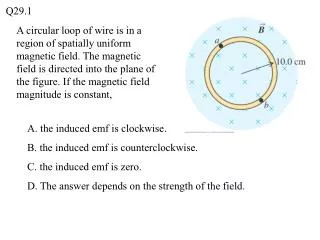
Magnetic Measurements of MICE Stators & PMs. Ben Shepherd MICE Target Workshop RAL, 13 December 2011. Contents. Stator Measurements Comparison to previous results Permanent magnet measurements New PMs T1 PMs. Initial scan.

E N D
Magnetic Measurements of MICE Stators & PMs Ben Shepherd MICE Target Workshop RAL, 13 December 2011
Contents • Stator • Measurements • Comparison to previous results • Permanent magnet measurements • New PMs • T1 PMs
Initial scan • Along x=y=0 – to determine peak positions and give us a zero offset • B0, B1 are transverse; B2 is longitudinal • Arbitrary units since not calibrated in all directions
Centre-finding scan • At each peak in B2 • Fit a quadratic function in x and y: • Solve to find minimum field
Results • Good agreement between centres measured by transverse and longitudinal fields • Centres all within 200µm in x and y
Comparison with other stators • Similar spread to T2 • Both worse than T3, which had a near-constant offset all the way through My nomenclature (probably inconsistent – sorry!) First stator I measured Second Third (this one was used in ISIS)
Measurements of new PMs • Measured eight new PM assemblies in the lab • PM mounted on a rotating stage • Hall probe attached to spring-loaded holder to keep it at the same distance from the PMs (about 1mm away) • Looking for the smallest change in Br with z
New PMs – measurement results In each row, the green cell is the best and the red the worst. Magnet #7 has the lowest relative standard deviation for peaks (0.7%) and the second-lowest for troughs (2.1%).So in terms of field uniformity, this is probably the best, followed by #4 and #6.
Measurements of old PMs • Used same technique to measure PMs from T1, just removed from ISIS • Variation of radial field: 2.1% for troughs, 2.6% for peaks • Compared to the new ones – ‘mid-range’