Download
1 / 23
230 likes | 273 Views
Detailed step-by-step instructions for post-flight assessment and recovery of the AESOP spectrometer payload, ensuring safe handling and proper decommissioning procedures.

E N D
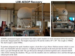
LDB AESOP Recovery AESOP is permanent magnet spectrometer that utilize spark chambers to track ionization left by fast moving electrically charged particles. The height of payload is 9ft and the width is 89” x 89”. The weight is 1900lbs. The shell weight is under 800lbs. To perform adequately the spark chambers require a fresh flow of gas (Neon / Helium mixture which is a non-toxic, non-flammable and non-corrosive). A flight gas bottle mounted on the deck provides the flow which enters a gas port through the shell. The gas then passes through an internal regulator and a solenoid shutoff value, before entering the chambers. The gas exits the chambers into two additional valves and then through an exhaust port on the shell.
Layout of the Payload There are two platform levels. Items labeled and outlined in red are located on the lower deck. Initially it is very important to secure the gas bottle and equalize the shell through the external 16psi relief valve. The Science Charge Controller and Black Box Recorded should be removed from the payload and placed in a cushioned container.
The recovery team must contact scientist reps (John Clem, Paul Evenson, Andrew McDermott or James Roth) ~2hours before cut-down to determine the status of the gas bottle pressure unless a prior communication revealed depression has occurred. Upon reaching the landing site inspect the condition of the payload on all sides. If serious damage is visible, immediately contact project reps to describe the condition and to receive specific instructions. If an emergency landing is required locally science reps John Clem or/and Andrew McDermott will be able to participate in the recovery effort. In this event the bottle will likely be charged and therefore the decompression procedure described inside this document should be followed at the landing site.
If payload damage is minor, the following should be followed: 1) Confirm bottle is depress Remove all side panels and locate bottle regulator Read the high pressure gauge. If the reading is less than 200psi, then shut off main bottle valve by rotating in clockwise direction. Remove bottle helmet, regulator and replace with bottle cap. The bottle cap will fly with bottle.
If the reading is greater than 200psi, slowly remove the gas hose end at the shell to allow gradual discharged. This shell port is connected to an internal gas regulator so pressure in the hose will be greater than the internal pressure shell. The gas hose pressure should be less 75psi. This procedure requires two wrenches: 11/16” and 3/4”. 11/16 wrench holds the stem in place while the 3/4 loosens the hose nut. Make a single quarter turn which should allow gas to pass between the threads. Gas exhaust flow can be fine tuned by tuning the hose nut. Monitor gas regulator and after the reading falls below 200psi shut off main bottle valve Remove regulator and replace with bottle cap. .
2) Locate thePressure Relief Valve on the lower section on the shell. Gently pull red lever until gas can be heard escaping the shell. Hold in that position until gas flow stops.
These feedthru ports are covered with insulation and tape for flight so assuming the payload does not wipe out a few trees on the way down, they will appear as shown in the photos Input Gas Shell port Pressure Relief Valve
3) LocateScience Charge Controller on lower deck opposite side to the gas regulator. Lift the red switch covers and then move the switches to the up position which disconnects the batteries and instrument from the charge controller Disconnect cables and remove hold down straps, then place Charge Controller into a well cushioned box. Batteries can be disposed.
4) LocateBlack Box Recorder on the lower deck behind the Science Charge Controller. (In White tape) (Need updated photo) Black box is actually white Disconnect single MS style connector on the end of the box. Lithium Batteries Data Splitter Box Remove tie down straps and box should then be free. Place box in cushion box
5) Remove antenna support which is basically 3 pieces of Al right angle. It is fasten to main frame by four bolts with lock nuts.
6) Remove electronics cable connector and gas supply hose The electronic cable is a large MS style connector that can be removed by hand The gas hose pressure should be 75psi so there may be a quick discharge noise during this task. This procedure requires two wrenches: open 11/16” and 3/4”. 11/16 wrench holds the stem in place while the 3/4 loosens the hose nut.
7) Remove the 4 tie down cables. Loosen the turn buckles which has 1/8” diameter hole at center. Remove shackle at deck. Remove 2 hold down fasteners. Need 2 x 1/2” wrenches
8) Remove shell from platform The shell weighs under 800lbs and can be lifted from the hold down points. Unfortunately one of the hold points is directly below the nose (cylinder extension containing an internal photomultiplier), therefore a special harness adapted for the non-symmetric shape must be used. The lift device used at launch site is a harness that has 4 cables, but two of cables are attached to a 21” ½” thick Al spreader bar. Since only one exist another one must be made in Palestine before recovery (2 free cable ends 60” and 2 spreader cables are 57”). After separation, the instrument should be strapped on to old tires before being transporting on a ground vehicle. The payload also should be shipped on air suspension truck if possible.
Recovery Instructions for MINIS Piggyback experiment Robyn Millan The piggyback is mounted on a plate enclosed in a blue-board foam insulation box mounted on the top platform beside the AESOP shell opposite side to the nose. The blue board foam box may be destroyed on landing, but if intact it will appear as in the photo to right. Disconnect the cables leading from the Piggyback to CSBF Science stack and hi-rate. These cables come out of the front of the Styrofoam box here: Inside the foam box you will find the following payload layout. All the instruments are mounted on a 40” long aluminum plate.
Power: In the event the power down command was not successful, the instrument could be active. So if possible remove the fuse plug on the front of the payload. The panel is mounted on the front of the foam box. Seen Here: To remove the fuse, push in and turn counter clockwise. This will ensure power to the instrument is disconnect. A close up is below.
If the foam box is destroyed and/or the panel is not easily located cut the main battery cable wires one at a time. They are red and black wires coming out of the battery box. Cut the pair of wires pictured here one at a time: This will completely severed power source from instrument. Removing the Lithium batteries After cutting the wires, the battery can now be removed from the battery box. It is taped closed, but bolted down. Cut the tape and remove the lid. Remove the Pink insulation inside box which surrounds the battery package wrapped in black rubber for electrical insulation. Remove and dispose battery of as appropriate. There are 8 cells, each 200g connected by two terminal blocks.
Recovering the Instrument. The full system is mounted on a 40”x 14” aluminum plate. This plate is bolted to the gondola top platform with four ½” x 6” bolts. It is recommended to unbolt this plate from the gondola platform in one piece, and recover as a whole. The bolts are located as pictured. Remove these bolts and lift the instrument off the gondola for retrieval.
IF INSTRUMENT PLATE CANNOT BE RECOVERED WHOLE Instrument Handling If the entire plate cannot be returned as a whole system the following instructions describe individual component removal and handling X-ray tube: The X-ray tube is located inside the pink foam insulation pictured here. It is held in place by a plastic collar that is bolted to the metal plate with four bolts. Pull the tube out of the collar to disconnect the cable which is plugged into the underside of the X-ray tube. Please keep the tube in the foam and package carefully. It is very FRAGILE. Photometer: The photometer is held on a stand by two hose clamps. Remove the hose clamps and disconnect the cable on the bottom end of the tube. Package the tube carefully it is FRAGILE. Computer: The computer is held to the mounting plate by four 4-40 machine screws with nuts on the top of the plate. All connections to the computer are easily unplugged. One small white coax cable at the top is unplugged right at the computer case. Another small black coax cable is also unplugged right at the computer. All other cables are taped down. Pull the tape up and unplug the cables at the connectors a few inches away from the computer. Power Box: The power box is held down by four 6-32 bolts and nuts. Unscrew these and disconnect cables from the rest of the payload. There are no live voltages here, just unplug any wire connected here and remove for packaging.
Shipping Requirements • If the instrument plate is recovered in tact : • -Double walled cardboard box • 48in x 18in x 23in -Minimum • Lined with cushioning • -White cardboard collimator tube • on photometer can be cut off 18in • from the end • -The remaining hole in the • photometer should be taped over to • limit light exposure. • The entirety of the box should be filled with padding/shipping material (i.e. peanuts or bubble wrap). This will ensure the safety of the fragile instruments. • The final destination of the payload will be: • Dr. Robyn Millan • Dartmouth College • Dept. of Physics and Astronomy • 6127 Wilder Lab. • Hanover, NH 03755 Collimator Cut Line
If instrument plate is not recovered in tact: • - Each instrument should be wrapped in packing material • -All the instruments may be shipped collectively in a double walled box, again full of packing material as the instruments are very fragile. • The final destination of the payload will be: • Dr. Robyn Millan • Dartmouth College • Dept. of Physics and Astronomy • 6127 Wilder Lab. • Hanover, NH 03755
Buoyancy Estimation of the Full Payload The internal volume of the shell (two 21" radius hemisphere with 13" straight mid-section, nose is 6" diameter and 16"long) provides a water displacement of 1720lbs.. 2" thick polyurethane insulation covering the shell surface gives an additional ~150lbs buoyancy. Shell with insulation displaces 1870lbs Gas bottle 120lbs 3/4 ply on the bottom shelf 190lbs Ignoring the remaining volumes on the payload, the subtotal water displacement is ~2200lbs (a lower limit).. It weighs 1905lbs, so the payload should have positive buoyancy however ~80% of the mass will be underwater..
Special Equipment: 1) Lifting Harness for Shell 2) Wrenches 1/2”, 11/16”, 3/4” Many adjustable wrenches, socket wrenches 3) Channel Locks 4) Bolt cutters 4) Tool to loosen turn buckles 5) Containers for Black Box Recorder, Science Charge Controller and Regulator 6) Cutting tool for stubborn straps 7) Used local tires for shipping material to cushion payload 8) Cardboard box with packing material at least 40” long x 12” wide x 16” deep for MINIS Piggy Back