Download

1 / 20
250 likes | 512 Views
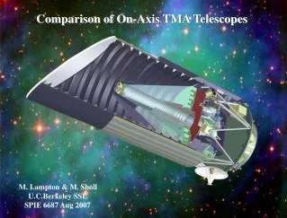
Comparison of On-Axis TMA Telescopes. M. Lampton & M. Sholl U.C.Berkeley SSL SPIE 6687 Aug 2007. Requirements for Surveys from Space. Field of View survey speed requirement the bigger, the faster! drives telescopes towards fully centered fields. Light Gathering Power

E N D
Comparison of On-Axis TMA Telescopes M. Lampton & M. Sholl U.C.Berkeley SSL SPIE 6687 Aug 2007
Requirements for Surveys from Space • Field of View • survey speed requirement • the bigger, the faster! • drives telescopes towards fully centered fields. • Light Gathering Power • directly driven by survey speed requirement • depth and signal to noise ratio • the bigger, the faster! • drives survey telescopes towards fully centered pupils. • Size and Stability of the Point Spread Function • size and stability directly influence signal to noise ratio • usual requirement is to be “diffraction limited” • further requirements from pixel size & image sampling • diffraction = lambda * f/number ≈ pixel size: • 10µm pixel / 1µm wavel f/10 • Broad Wavelength Coverage • drives towards all-reflector designs • Stray Light, Stray Heat • drives towards well baffled designs • NIR emphasizes need for a well defined real exit pupil • Limited package diameter and length • favors on-axis centered pupils • drives telephoto ratio
Telescope Landscape f/1 - PAUL BAKER Off Axis TMAs Korsch SCHMIDT SPHERE + 4 MIR CORR SCHMIDT CASS R-C + FLATTENER Speed CASSEGRAIN RITCHEY CHRETIEN f/10 - PARABOLOID f/100 - | 0.1 | 0.3 | 1 | 3 | 10 Full field angle, degrees TMA group can have Seidel aberrations = 0 and a flat field without refractive elements
Three-Mirror Flexibility! With nine adjustables, meeting six optical requirements (Seidels=0, focal length, field curvature) leaves a 3-space of design freedom.
Some Three-Mirror Telescopes • Fast, on-axis field • Paul 1935 • Baker 1969 • Robb 1978 • McGraw 1982 • Epps & Takeda 1983 • Willstrop 1984 • Angel 2000 • Slow or Fast Off-axis field • Cook 1979 • IKONOS etc • Multi Spectral Imager • DESTINY • JWST • Slow, on-axis field • Korsch 1972....1980 Willstrop LSST DESTINY
D. KorchD. Korsch, Appl. Opt. 11, 2986, 1972; Appl. Opt. 16, 2074, 1977; Appl. Opt. 19, 3640, 1980. • Explored a portion of TMA space... • Retained the requirement for a centered pupil • Retained the requirement for a centered field • Retained the requirement for a telephoto advantage >> 1 that is essential for space astronomy • Retained the requirement for a real exit pupil, by arranging that the tertiary mirror light crosses the TM axis en route to its focus • Immediately faced the blockage problem • Explored various ways to extract all the light from the principal axis • Came up with four alternative optical layouts.
Korch’s Two Key Ideas • Using the flexibility of TMAs, arrange for the Cassegrain focus and the exit pupil to be colocated along their common axis. • Using the flexibility of TMAs, arrange the magnifications so the Cassegrain field size is smaller or larger than the exit pupil. • if CF is smaller: put an extraction mirror there to separate the Cassegrain light from the final focus light. This will punch a hole in the center of the exit pupil. But there’s already a hole there – the shadow of the secondary mirror! Nothing is lost. => Full Field group. • if CF is larger: put an extraction mirror there anyway. This will punch a hole in the center of the field of view. Some portion of the survey field is lost, but full throughput is obtained throughout the remaining annular field. => Annular Field group.
Full Field TMA – config I 6 surfaces Fig1.OPT X Z pitch mir? Curv Aspher Diam diam ------:---.-------:------:------:----.-------:---.-----:------:-----:--- 0 : 0 : 0 : mir : -0.3126554? -0.98063? 2.1 : 0.6 : 0 : -1.25 : 0 : mir : -0.9772446? -3.48512? 0.6 : : 0 : 0.8 : 0 : mir : -0.6467372? -0.62193? 0.6 : : 0 : -0.15 : -15 : mir : 0 : : 0.4 : 0.1 : -0.8 : 1.2356406? -60 : mir : 0 : : 0.5 : : 0.8 : 1.2356406e 90 : FP : 0 : : 0.5 : : Figure 1 (Upper): A full field TMA with the tertiary mirror on the main axis, configuration I . Stray light and stray heat baffling are not shown. The Cassegrain focus field is small, and passes through the hole in the angled extraction mirror EM to illuminate the tertiary mirror TM. (Lower): prescription for this TMA example. Coordinates are in meters, angles are in degrees, curvatures are in reciprocal meters.
Full Field TMA – config II 6 surfaces Fig2.OPT X Z pitch mir? Curv Aspher Diam dia ---.---:---.-------:------:-------:---.-------:---.-----::------:----:---- 0 : 0 : 0 : mirPM : -0.4059429? -0.98380?: 2.1 :0.5 : 0 : -0.9 : 0 : mirSM : -1.1423599? -2.55954?: 0.7 : : 0 : 0.44 : -45 : mirEM : 0 : :: : : 0.9 : 0.44 : 90 : mirTM : -0.7074022? -0.66695?: 0.6 : : -0.9 : 0.44 :-105 : mirFM : 0 : :: : : 0.8 : 1.4214955? 60 : FP : 0 : :: : : Figure 2 (Upper): Full field TMA with the tertiary mirror off the main axis (configuration II in the notation of Korsch 1977) . Stray light and stray heat treatments are not shown. This arrangement is similar to the configuration I, except that the small central CF field is reflected to the TM rather than passing through the hole in the extraction mirror. (Lower): prescription for this TMA example.
Annular Field – config I 5 surfaces Fig3.OPT X Z pitch Curvature Aspher Diam diam Mirror? ---.---:---.-----:-----:---.-------:---.-------:------:------::----------:--- 0 : 0.0 : : -0.2078487? -0.9831629? 2.1 : 0.5 ::mir pri : 0 : -2.0000 : : -1.0055416? -1.9357465? 0.6 : ::mir sec : 0 : 1.2 : : -0.8001814? -0.6005692? 0.7 : ::mir tert : 0 : 0.4 : 45 : : : : ::mir fold : 0.867? 0.4 : 90 : 0 : : 0.6 : ::FP : Figure 3 (Upper): An annular-field Korsch TMA has its Cassegrain field much larger than the exit pupil. In configuration I shown here, the light from the tertiary mirror is extracted at the exit pupil by a small flat mirror. The tertiary magnification is ~1.5x. (Lower): prescription for this TMA example.
Annular Field – config II 5 surfaces Fig4.OPT X Z pitch Curvature Aspher Diam diam Mirror? ---.---:---.-----:-----:---.-------:---.-------:------:------::----------:--- 0 : 0.0 : : -0.2049195: -0.9826577: 2.1 : 0.5 ::mir pri : 0 : -2.0000 : : -0.9479331: -1.7968547: 0.6 : ::mir sec : 0 : 1.0 : 45 : : : : ::mir fold : -0.77 : 1.0 :-90 : -0.7506071: -0.6114183: 0.7 : ::mir tert : 0.88 : 1.0 : 90 : 0 : : 0.6 : ::FP : Figure 4 (Upper) : An annular field Korsch configuration II TMA. The extraction mirror on the axis directs the Cassegrain field CF onto the tertiary mirror TM. The hole in the EM allows the TM to illuminate the focal plane FP. The exit pupil lies within the hole in the annular flat mirror. A conical cold stop structure can extend from EP to the FP without blocking light. (Lower): the prescription for this TMA example.
Strengths & Weaknesses • Full Field TMAs • no hole in the middle of the field • very wide range of EFLs available • Annular Field TMAs • slower Cass section => somewhat more tolerant PM-SM despace • inherent baffling, particularly with II’s complete cold stop • For low geometric distortion.... • need large tertiary magnification and/or concave focal plane • final f/number = Cass f/number * tertiary magnification • automatic with all the FFTMAs whose tert mag is large • can also be had with the AFTMAs provided system is slow enough • concave focal plane can improve distortion performance • example: Grange et al 2006, Refregier et al 2006 “DUNE” • get focal plane center of curvature nearly centered on exit pupil • linearly convert angles at exit pupil into positions on focal plane
Some Contemporary Studies • FFTMA configuration I • ESA “Wide Field Imager” telescope project, European Space Agency CDF Study Report CDF-46(A), 2006. • AFTMA configuration I • CNES “DUNE” project, R. Grange et al., Proc. SPIE 6265, #49, 2006; . A. Refregier et al., Proc SPIE 6265 #1Y, 2006. • AFTMA configuration II • US DoE LBNL “SNAP” project, M. Sholl et al., Proc. SPIE 5487, 73-80, 2004, M. Sholl et al., Proc. SPIE 5899, 27-38, 2005. • NAOJ project, K. Nariai and M. Iye, astro-ph/0504514; Pub.Astron.Soc.Jap. 57, 391-397, 2005. • CNES Pleiades project,D. Fappani and H. Ducollet, Proc. SPIE 6687 (this conference), 2007.
ESA Wide Field ImagerEuropean Space Agency CDF Study Report CDF-46(A), 2006. • Full Field TMA configuration I • Relatively short Cassegrain focus and small linear Cass field • Large tertiary magnification ~5:1
DUNER.Grange et al., 2006; A.Refregier et al., 2006 • Annular Field TMA, configuration I • Reasonably slow Cassegrain focus • Relatively large tertiary magnification ~ 4:1 • Slightly concave focal surface • Essentially “zero distortion” performance allows TDI
SNAPM.Lampton et al. 2002 et seq.; M.Sholl et al., R Besuner et al. this conference • Annular Field TMA configuration II • Relatively long Cassegrain focus allows field mask, shutter • Relatively small tertiary magnification, 1.5:1 • Flat focal plane, unvignetted annulus 0.34 to 0.77 degrees radius
NAOJ 30m ProjectK.Nariai and M.Iye, 2005 • Annular Field TMA configuration II • Long Cassegrain focal length • Field is split at Cassegrain focus into two halves at M4 • 1:1 tertiary magnification • Mirror M6 extracts light to focal plane with almost no associated central blind zone
PLEIADESD.Fappani & H.Ducollet, this conference • Annular Field TMA configuration II • Field is only partially utilized • Relatively long Cassegrain focal length • Relatively modest tertiary magnification = 1.4
References 1. M. Paul, Rev. Optics 14, 169, 1935. 2. J. Baker, IEEE Trans A.E.Sys. 5, 261, 1969. 3. R. Angel et al., Proc. SPIE 332, 134, 1982. 4. D. Willstrop, MNRAS 210, 597, 1984. 5. L.G. Cook, Proc. SPIE 183, 207-211, 1979. 6. C. Atkinson et al., Proc. SPIE 6265, 2006 and references therein. 7. R. N. Wilson "Reflecting Telescope Optics I" Springer, Berlin 1996, pp.215-231. 8. D. Korsch, Appl. Opt. 11, #12, 2986-2987, 1972. 9. D. Korsch, Appl. Opt. 16, #8, 2074-2077, 1977. 10. D. Korsch, Appl. Opt. 19, #21 3640-3645, 1980. 11. European Space Agency CDF Study Report CDF-46(A), 2006. 12. R. Grange et al., Proc. SPIE 6265, #49, 2006. 13. A. Refregier et al., Proc SPIE 6265 #1Y, 2006. 14. M. Lampton et al., Proc. SPIE 4849, 215-226, 2002. 15. M. Lampton et al., Proc. SPIE 5166, 113-123, 2003. 16. M. Sholl et al., Proc. SPIE 5487, 73-80, 2004. 17. M. Sholl et al., Proc. SPIE 5899, 27-38, 2005. 18. D. Fappani and H. Ducollet, Proc. SPIE 6687 (this conference), 2007. 19. K. Nariai and M. Iye, astro-ph/0504514; Pub.Astron.Soc.Jap. 57, 391-397, 2005.