Download
1 / 10
110 likes | 165 Views
Learn about gear terminology, types, advantages, and disadvantages such as spur gears, bevel gears, worm gears, rack and pinion systems, and helical gears for efficient power transmission.

E N D
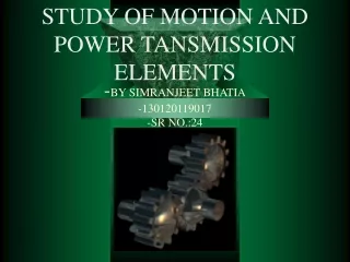
-BY SIMRANJEET BHATIA-130120119017-SR NO.:24 STUDY OF MOTION AND POWER TANSMISSION ELEMENTS
OUTSIDE DIAMETER PITCH DIAMETER DIAMETRAL PITCH = TOOTH SIZE ROOT DIAMETER CENTERDISTANCE GEAR TERMINOLOGY
D2 TANGENT PITCH CIRCLES D1 D1 + D2 2 CENTER-TO-CENTER DISTANCE = CC DIST MATING SPUR GEARS
CHAIN DRIVE • Easier to remove/replace than belts • Compact • Somewhat flexible • Relatively inexpensive • Can handle heat, dirt, weather exposure (when properly lubricated)
GEAR DRIVE • Gears are most often used in transmissions to convert an electric motor’s high speed and low torque to a shaft’s requirements for low speed high torque: • Gears essentially allow positive engagement between teeth so high forces can be transmitted while still undergoing essentially rolling contact • Basic Law of Gearing: –A common normal (the line of action) to the tooth profiles at their point of contact must, in all positions of the contacting teeth, pass through a fixed point on the line-of-centers called the pitch point –Any two curves or profiles engaging each other and satisfying the law of gearing are conjugate curves, and the relative rotation speed of the gears will be constant
BEVEL GEAR SPUR GEAR • Teeth are parallel to the axis of the gear • Advantages • Cost • Ease of manufacture • Availability • Disadvantages • Only works with mating gear • Axis of gear is parallel • Gear axis at 90°, based on rolling cones • Advantages • Right angle drives • Disadvantages • Get axial loading which complicates bearings and housings
WORM GEAR RACK AND PINION • The rack and pinion gear is used to convert between rotary and linear motion. • Gears that are 90° to each other • Advantages • Quiet / smooth drive • Can transmit torque at right angles • No back driving • Disadvantage • Most inefficient due to excessive friction (sliding) • Needs maintenance • Could have straight or bevel teeth • Provides less backlash • Greater feedback
HELICAL GEARS • Teeth are at an angle to the gear axis (usually 10° to 45°) – called helix angle • Advantages • Smooth and quiet due to gradual tooth engagements (spur gears whine at high speed due to impact). Helical gears good up to speeds in excess of 5,000 ft/min • More tooth engagement allows for greater power transmission for given gear size. • Disadvantage • More expensive • Resulting axial thrust component