Download
1 / 46
470 likes | 609 Views
Several Topics in Recent Accelerator Studies . Weiren Chou Fermilab June 10, 2003 Presentation to the Midwest Accelerator Physics Meeting June 10-11, 2003, ANL. Outline. (1) Booster modeling (2) Space charge (3) Barrier RF stacking. Fermilab Accelerator Complex. (1) Booster Modeling.

E N D
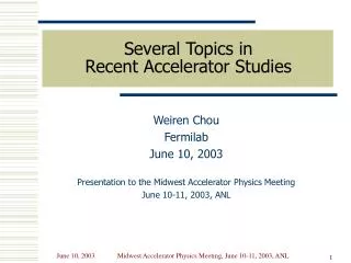
Several Topics inRecent Accelerator Studies Weiren Chou Fermilab June 10, 2003 Presentation to the Midwest Accelerator Physics Meeting June 10-11, 2003, ANL Midwest Accelerator Physics Meeting, June 10-11, 2003, ANL
Outline (1) Booster modeling (2) Space charge (3) Barrier RF stacking Midwest Accelerator Physics Meeting, June 10-11, 2003, ANL
Fermilab Accelerator Complex Midwest Accelerator Physics Meeting, June 10-11, 2003, ANL
(1) Booster Modeling • The dogleg effect (Sasha’s talk) • The first 3 milliseconds • Chromaticity modeling • Model improvement • Booster power supply experiments at E4R Midwest Accelerator Physics Meeting, June 10-11, 2003, ANL
Booster Beam Loss(courtesy R. Webber) Midwest Accelerator Physics Meeting, June 10-11, 2003, ANL
First 3 milliseconds in the Booster • Logitudinal loss • The measured Booster longitudinal acceptance is small: 0.15-0.2% • The measured linac beam momentum spread is about 0.13% • When the beam is bunched, the momentum spread increases to 0.3% • This exceeds the acceptance and results in loss • Transverse loss • The transverse acceptance is: A = {maxN/}1/2 + Dmax p/p + c.o.d. • The magnet good field region is about 1.2 inch • For regular max and Dmax, the maximum allowable N is about 16 • But the doglegs blow up the lattice function and reduce N to about 8 • The incoming linac beam is 7 • Space charge dilutes the emittance during the multiturn injection, resulting in loss. Midwest Accelerator Physics Meeting, June 10-11, 2003, ANL
First 3 milliseconds in the Booster(cont…) When beam energy goes up, the situation improves rapidly: • Longitudinal: • ΔE/E • 1/β2 • Δp/p = (1/β2) ΔE/E • Transverse: • Dogleg focusing strength: 1/f = 2/L 1/p2 • Beam size due to adiabatic damping: = N/ • Space charge effect 1/2 In the middle and late stage of the cycle, other schemes will contribute to the beam loss (e.g., transition crossing, coupled bunch instability), but which is beyond this topic. Midwest Accelerator Physics Meeting, June 10-11, 2003, ANL
Chromaticity Modeling = (lat) + (dogleg) + (mag sext) + (chrom sext) • Goal: To have a spreadsheet relating the sextupole current to the machine chromaticity throughout the cycle • The task is complicated by two factors: • The dogleg effect, which perturbs the local lattice function and has an energy dependence (calculable) • The main magnets have large sextupole component, which comes from both the body part and the end packs (need measurement) Midwest Accelerator Physics Meeting, June 10-11, 2003, ANL
Chromaticity Calculation (x)(y) • Bare lattice (Lat) -9.16679 -7.03638 • Lat + dogleg -9.57427 -7.01265 • Lat + body sext -23.55770 11.65977 • Lat + body sext + dogleg -23.40371 11.00271 • Lat + body sext + chrom sext + dogleg 0.04399 -0.18496 • Lat + body sext + chrom sext (no dogleg) 3.67119 -11.11968 The doglegs' direct contribution to the chromaticity is small. But their impact on the chromaticity is significant because of the big change of local and D at the chromaticity sextupoles. Midwest Accelerator Physics Meeting, June 10-11, 2003, ANL
Field Measurement at E4R A mole used for dc field measurement Midwest Accelerator Physics Meeting, June 10-11, 2003, ANL
Main Magnet Sextupole Component • Two independent measurements: • Field measurement at the E4R • Chromaticity measurement at the Main Control Room • The two teams did not talk to each other on purpose (a blind check) • The results are found to be in good agreement at 400 MeV • Work in progress for ac measurement Midwest Accelerator Physics Meeting, June 10-11, 2003, ANL
Main Magnet Sextupole Measurements(cont…) F magnet D magnet Body only Body+ends Body only Body+ends Chrom meas. Chrom meas. Midwest Accelerator Physics Meeting, June 10-11, 2003, ANL
Model Improvement • Trim quads • 24 H, 24 V • Weak, about 2% of the main quad strength • But perturbations on beta function and tune are big • MAD output does not seem to match the observation • Steering magnets • Not in the model yet • Alignment errors • Model uses old data, needs updated ones • Aperture scanning • Need to be re-done Midwest Accelerator Physics Meeting, June 10-11, 2003, ANL
Power Supply Experiments at E4R • Motivation: To make the existing RF system capable to accelerate more particles • Experiment 1: Reduce the repetition rate from 15 Hz to 12 Hz • Experiment 2: Dual harmonic resonant (15 Hz + 12.5% 30 Hz) • Purpose: To reduce the peak RF power by 25% Midwest Accelerator Physics Meeting, June 10-11, 2003, ANL
Booster Cell with 2nd Harmonic(courtesy D. Wolff) Midwest Accelerator Physics Meeting, June 10-11, 2003, ANL
Dual Harmonic Current and dI/dt (3 cases: dual 0%, 9%, 18%; courtesy D. Wolff) dI/dt Current I Midwest Accelerator Physics Meeting, June 10-11, 2003, ANL
(2) Space Charge • Simulation codes • ESME (P. Lucas, J. MacLachlan) • ORBIT (F. Ostiguy, W. Chou) • Synergia (P. Spentzouris, J. Amundson) • Tune footprint • Emittance blowup during and after the injection • IPM (Ion Profile Monitor) measurement • Code benchmarking Midwest Accelerator Physics Meeting, June 10-11, 2003, ANL
Linac 805 MHz Microbunches(ESME, courtesy P. Lucas) One microbunch with Δp/p =0.13% Multiturn injection Midwest Accelerator Physics Meeting, June 10-11, 2003, ANL
Tune Footprint(ORBIT, varying beam intensity) Laslett tuneshift: 0.3 Midwest Accelerator Physics Meeting, June 10-11, 2003, ANL
Emittance Histogram(ORBIT) Percentage (%) With space charge No space charge Emittance Midwest Accelerator Physics Meeting, June 10-11, 2003, ANL
Emittance Growth(ORBIT, 11-turn injection, varying beam intensity) inj Fast growth during injection Slow growth after injection No space charge Turn Midwest Accelerator Physics Meeting, June 10-11, 2003, ANL
IPM Measurement(raw data) 40 mA, 10-turn injection 20 mA, 10-turn injection Fast growth Slow growth inj 45 turns Midwest Accelerator Physics Meeting, June 10-11, 2003, ANL
IPM Measurement(processed data, courtesy P. Spentzouris) November data December data inj Midwest Accelerator Physics Meeting, June 10-11, 2003, ANL
Emittance Growth during Injection(varying space charge effects) Transverse sc only Transverse + Longitudinal Longitudinal sc only No space charge Turn Midwest Accelerator Physics Meeting, June 10-11, 2003, ANL
Space Charge Code Benchmarking(12th ICFA Mini-Workshop, April 2-4, 2003, Oxford, England) • Data: CERN PS experiment on Montague resonance (2x - 2y = 0) • Participants in this benchmarking: • F. Jones (Accsim) • A. Luccio (Orbit) • J. Holmes, S. Cousineau (Orbit) • A. Adelmann (GenTrackE) • H. Qin (Best) • I. Hofmann (Micromap) • W. Chou, F. Ostiguy, P. Lucas (Orbit) • J. Qiang, R. Ryne (IMPACT, ML/I) • D. Johnson, F. Neri (Simpsons) Midwest Accelerator Physics Meeting, June 10-11, 2003, ANL
tune diagram(betatron periods per turn without space charge) Midwest Accelerator Physics Meeting, June 10-11, 2003, ANL
Comparison with simulation (Gaussian/coasting beam)- observed broader than in simulation Midwest Accelerator Physics Meeting, June 10-11, 2003, ANL
(3) Barrier RF Stacking • Motivation: To overcome the Booster bottleneck problem and double the proton intensity on the production target. • Method: • To stack two Booster bunches into one MI bucket by using a barrier RF system. • This is possible because the Main Injector momentum acceptance (0.4 eV-s) is larger than the Booster bunch emittance (0.1 eV-s) • Ng’s simulation • Barrier RF system and bench test Midwest Accelerator Physics Meeting, June 10-11, 2003, ANL
Booster Energy Loss(courtesy R. Webber) Midwest Accelerator Physics Meeting, June 10-11, 2003, ANL
Stacking Goals • Goal for Run2 – To increase protons per second (pps) on the pbar target by 50% • Baseline: 5e12 every 1.467 sec • Goal: 2 x 5e12 every 2 sec • Goal for NuMI – To increase pps on the NuMI target by 60% • Baseline: 3e13 every 1.867 sec • Goal: 2 x 3e13 every 2.333 sec Midwest Accelerator Physics Meeting, June 10-11, 2003, ANL
Method • A straightforward way is to inject two Booster batches into the MI, confine them by RF barrier buckets, then move the barrier to compress the beam. • But the compression must be slow (adiabatic) in order to avoid emittance growth. This would lengthen the injection process and thus reduce protons per second (pps) • A better way (first proposed by J. Griffin) is to inject Booster batches off-axis so that the injection can be continuous Midwest Accelerator Physics Meeting, June 10-11, 2003, ANL
Two Types of Barrier Stationary barrier +V -V Moving barrier +V -V Midwest Accelerator Physics Meeting, June 10-11, 2003, ANL
Injection Beam Off-Axis(courtesy K.Y. Ng) Midwest Accelerator Physics Meeting, June 10-11, 2003, ANL
2-Batch Stacking(Run2) Midwest Accelerator Physics Meeting, June 10-11, 2003, ANL
12-Batch Stacking(NuMI) Midwest Accelerator Physics Meeting, June 10-11, 2003, ANL
Finemet Core Midwest Accelerator Physics Meeting, June 10-11, 2003, ANL
High Voltage Fast Switch Midwest Accelerator Physics Meeting, June 10-11, 2003, ANL
Building a Barrier RF System A Fermilab-KEK-Caltech team Barrier RF power supply Midwest Accelerator Physics Meeting, June 10-11, 2003, ANL
Building a Barrier RF System(cont…) Barrier RF cavity Midwest Accelerator Physics Meeting, June 10-11, 2003, ANL
Testing a Barrier RF System Two barriers per MI period One barrier trigger current primary voltage gap voltage Midwest Accelerator Physics Meeting, June 10-11, 2003, ANL
Testing a Barrier RF System(cont…) • The required burst length is 150 ms (2.2 Booster cycles); achieved 200 ms. • The required peak voltage is 6 kV; achieved 4 kV. • Waiting for two larger switches to raise the voltage to 6 kV. Burst length Midwest Accelerator Physics Meeting, June 10-11, 2003, ANL
Finemet vs. Ferrite (4M2) Midwest Accelerator Physics Meeting, June 10-11, 2003, ANL
Finemet vs. Ferrite (4M2)(cont…) Midwest Accelerator Physics Meeting, June 10-11, 2003, ANL
Barrier RF Stacking vs. Slip Stacking • One main advantage of barrier RF stacking is smaller beam loading effect thanks to lower peak beam current • Another “advantage” is that we didn’t know much about this method and have never tried. (By contrast, we already know how hard slip stacking is.) Midwest Accelerator Physics Meeting, June 10-11, 2003, ANL
Key Issue • Booster beam must have a small E/E to start with (required E about 6 MeV) • This means one has to control the instability of the Booster beam: • longitudinal damper (D. Wildman) • RF frequency modulation for Landau damping (TBA) • bunch rotation prior to extraction (K. Koba) Midwest Accelerator Physics Meeting, June 10-11, 2003, ANL
Questions? Midwest Accelerator Physics Meeting, June 10-11, 2003, ANL