Thermal and Mechanical Support Considerations for Beam Alignment at SLAC
330 likes | 449 Views
This document discusses critical factors influencing thermal and mechanical stability in beam alignment at SLAC. It highlights trajectory tolerances, thermal distortions, and the necessity of stable foundations and support structures. Key aspects include temperature coefficients, magnet tolerances, alignment strategies, and techniques for monitoring stability. Also examined are the implications of mechanical and electrical offsets in Beam Position Monitors (BPMs) and quadrupoles during beam-based alignment procedures. Proper design and maintenance of these systems are essential for achieving ultra-straight trajectories.

Thermal and Mechanical Support Considerations for Beam Alignment at SLAC
E N D
Presentation Transcript
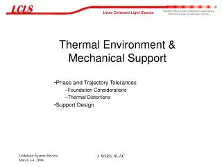
Thermal Environment & Mechanical Support Phase and Trajectory Tolerances Foundation Considerations Thermal Distortions Support Design J. Welch, SLAC
Phase error tolerance implications • 2 micron rms trajectory tolerance (perfect undulator) • Segment to segment strength variation of 1.5 x 10⁻⁴ • Temperature coefficient of NdFeB is 0.1%/C • Undulator compensation via Ti/Al assembly) magnet temperature tolerance ~ +-0.2 C • Vertical undulator alignment 50 mm causes 10 degrees of additional slippage 2 mm deviation from straight over 10 m is about the average curvature of the Earth’s surface J. Welch, SLAC
Path Length Increases due to Bumps • LCLS: A < 3.2 mm • LEUTL: A < 100 mm • VISA: A < 50 mm from H-D Nuhn J. Welch, SLAC
Alignment and Stability Strategy • Three layers of defense against trajectory errors • Beam based • fast orbit feedback for launch errors • full BBA with multiple beam energies to measure BPM and Quad offsets. • Wire Positioning System and Hydrostatic Leveling System • HLS systems have shown good long term stability • WPS system have shown good short term stability • Make foundation and supports as stable as possible • thermal stability, geotechnical, and support mechanical design J. Welch, SLAC
Beam Based Alignment If errors are too big they must be fixed rather than “corrected for” • BBA is the fundamental LCLS tool to obtain and maintain ultra-straight trajectories over long term. • Corrects for • BPM mechanical and electrical offsets • Field errors, (built-in) and stray fields • Field errors due to alignment error • Input trajectory error • Does not correct undulator alignment errors • Establishes a best fit straight line electron trajectory • Procedure • Take orbits with three or more very different beam energies, calculate corrections • Move quadrupoles and/or adjust steering coils to correct orbit • Disruptive to operation offsets don’t depend on energy 1/month is ignorable, 1/day is intolerable J. Welch, SLAC
BPM and Quad Stability Requirements • After BBA, changes of BPM offsets will be seen erroneously as orbit errors • Stability of BPM mechanical and electrical offsets determine trajectory stability • need BPM stability of ~ 2 mm rms • BPM’s have to be mechanically more stable than all other components • Known BPM motions are taken out in software Quad stability requirements are more like 5 microns J. Welch, SLAC
Support and Monitoring Schematic J. Welch, SLAC
Foundation Instability J. Welch, SLAC
Settlement Implications for LCLS • Expect settlement of order • ~ 300 - 1000 mm / year = 1 - 3 mm / day, • not well correlated with location • Good alignment lasts only a day or so • Mover range cannot accommodate much of the drift; need another mechanism with plenty of range and periodic realignment J. Welch, SLAC
Foundation Design Guidance • Uniformity of construction along length • avoid fill areas which settle much faster • try to avoid kinks, gentle bends are more tolerable • Strong thick floor • ~ 3 ft, essentially monolithic • Buried/tunneled • research yard has poor stability • good thermal insulation • Water table considerations • desire either wet or dry all year • keep sandstone wet between exposure and concrete J. Welch, SLAC
Vibration • Normally vibration amplitudes are much less than 1 micron, typically 10 - 100 nm. • ~10 nm measured on top of berm. • Possible areas of concern • air handling units • passage of vehicles over undulator hall tunnel. • Pointing sensitivity ~ 10-7 radians (1/10 angular divergence) • e.g. 10 Hz -> yrms ~ 1 micron • Q factors for equipment can be 100’s, supports need to be checked J. Welch, SLAC
Thermo-Mechanical Instabilities • Dilatation (ordinary thermal expansion) • Warp caused by thermal gradients (heat flux) J. Welch, SLAC
Dilatation Support column height from (fixed?) bedrock 3+ meters. Temperature coefficient for Anocast 12 ppm/C Temperature change for 1 micron vertical motion is 0.03 C --> BBA re-measure at 0.06 C change -->stability during BBA procedure 0.03 C/ 8 hr, (~1 degree/week) J. Welch, SLAC
Warping from Heat Flux • Long beams bend easily if there is a heat flux across them. • Heat fluxes can arise from • Temperature differences between walls and radiant heat transfer • Air temperature differences • Contact with supports or other materials • It is easy to show the bar goes to “average” temperature T1 T2 J. Welch, SLAC
Heat Flux Example • Heat flow a the bar for 1 degree temperature difference J. Welch, SLAC
Heat Flux Distortions • Bar Warp d L = 3 m, titanium 3 W/m2 -> 2 micron warp for an undulator segment 2 microns is the walk-off tolerance, -> Max wall temperature difference is ~1 degree C J. Welch, SLAC
Thermal Environment • Air temperature in both time and space • Surface temperatures • Heat sources and sinks J. Welch, SLAC
Air Temperature Illustration Air Temperature Match MMF temperature J. Welch, SLAC
more temp specs J. Welch, SLAC
Girder Concept If the girder is truly stable, linearly correlated motion along the girder can be identified and corrector for. The longer the girder the better • Stability of bedrock is not good (1-3 mm/day) • Long girder to provide good relative alignment stability • Length > gain length ( ~ 5 m) • Reduce the number of supports req’d J. Welch, SLAC
Girder Concept J. Welch, SLAC
Good overall long term stability common choice for metrology and magnet measurement benches Large thermal mass averages temperature fluctuations, good passive stability Low thermal expansion coefficient ~ 1/2 cte of steel, similar to ceramics Reasonable cost in large sizes ~ $40,000 for 12 x 0.8 x 0.8 m, finished and delivered (enough for 3 undulator segments) Low thermal conductivity sensitive to heat fluxes Variable mechanical properties Doesn’t take a tap hard to add features Not ductile handle with care Heavy Why Granite? PRO CON J. Welch, SLAC
Aluminum tubes with temperature stabilization Steel or cast iron girders Engineered stone (Anocast) Carbon reinforced plastic tube trusses Specialized concrete NLC technology SiC girders! Other Girder Options J. Welch, SLAC
Support Assembly Concept J. Welch, SLAC
Earthquake bracing J. Welch, SLAC
Support in Tunnel J. Welch, SLAC
Adjustable support platform J. Welch, SLAC
Testing a 6 m piece from Barre Vt for long term stability - start this summer does it slowly sag? how much does it warp with temperature and humidity changes in the surrounding tunnel? What does sealing do? does insulation help? how much? thermal stabilization time? Prototype mounting schemes for adjustable support platform and kinematic supports Support R&D J. Welch, SLAC
Granite manufacture and shipping time 10 weeks for first item don’t know at what rate they can be produced, need at least 11. Quarry closed Jan - Mar Stabilization time ~ 2 months, before ready to measure Integration into installation schedule under development Granite beams ~ $500,000 Other support costs ~ $500,000 Thermometry, kinematic supports, insulation, tubes, plates, eq bracing, etc Schedule & Cost J. Welch, SLAC
Extra Slides J. Welch, SLAC
Temperature specs J. Welch, SLAC
Basic Tolerance Requirements from Simulations • Saturation length (86 m) increases by one gain length (4.7 m), for the 1.5 Angstrom case if there is: • 18 degree rms beam/radiation phase error • 1 rms beam size ( ~ 30 mm) beam/radiation overlap error. J. Welch, SLAC
Assembly Concept exploded J. Welch, SLAC