Download
1 / 13
130 likes | 238 Views
Explore the innovative synchronous DCTI method for clock recovery in ATM services, detailing signal analysis, function definitions, and system implementation. Find out about the advantages compared to traditional methods.

E N D
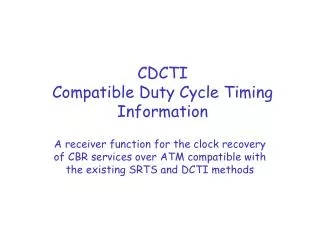
DCTIDuty Cycle Timing Information A synchronous method for the clock recovery in the transport of Constant bit rate services over ATM
DCTI – the idea • Let’s consider the XOR (y) between the network clock divided by an integer D (cd) and the user clock divided by an integer Ds (cds). • The y signal is a sort of PWM and the modulating signal dc (y duty cycle) contains the information about the relation between the 2 clocks. • The problem is how to extract such info, how to code it and how to use it at the receiver in order to recovery the user clock.
DCTI – the idea • Let’s assume that both at the transmitter and at the receiver the signal dc and dc’ are available • Let’s define ti the temporal distance between the i-th sample of dc and and the i-th sample of dc’. • The 2 user clocks will be locked if ti = ti+1 for each i > io. • Our goal is to get a close forme expression involving just the variable dc, dc’ and ti. In this way we could control a VCXO (Voltage Controlled Quarz Oscillator) keeping ti constant.
DCTI – the idea Making a few computations we can easily obtain the following results: So we can define a new function dcT at the transmitter and its homologous dcR at the receiver:
DCTI – the idea • Let’s consider at the receiver the difference function dcT-dcR, which has got the following mathematical expression: • This function has got the following graphical rapresentation As you can see it still depends from the parameter tT
DCTI – the idea • But if we finally consider the following function: • This function has got the following graphical rapresentation It is constant respect to tT and this is the reason why it can be used for our controlling porpose as following: fi = fi-1 + k (xi – xi-1) Where fi is the output frequency of the VCXO related to the i-th DCTI sample received
Receiver Control Variable Generator Oscillator System fs’ fs DCTI Generator ATM Network DCTI Generator fn DCTI – Implementation Not considering the quantization process and a few other mathematical considerations here following an high level overview of the system:
DCTI – DCTI Generator This is the blocks shema of the DCTI Transmitter Which implements the DCTI signal and samples it each N fs cycles:
DCTI – Control Parameter Generator This is the blocks shema of the Control Parameter generator
DCTI – Oscillator System This is the blocks schema of the Oscillator System The clipper has been introduced in order to avoid instability condition. Note: The stability study of the system and others mathematical considerations are not matters of this persentation. For more detailed information please refer to my thesis (Un nuovo sistema di recupero del clock per segnali a bit rate costante in ambiente ATM, Università degli Studi di Palermo, DIE, Laureando Salvatore Valenza – Relatore Prof. Matteo Campanella, 1998) or contact me at SalvoValenza@msn.com
DCTI vs SRTS Long term oscillation Locking time
DCTI vs SRTS Frenquency variation during the locking time Long time average error
DCTI – Advantages Advantages with repect to the ITU raccomended method SRTS: • The locking time is between the –50% and the –82% with respect to the SRTS one • The Long term oscillation is between –25% and –55% with respect to the SRTS one • The frequency variation is between – 99.4% and –99.8% with respect to the SRTS one • The DCTI is almost unaffected by any cell loss because of the limited variations of the recovered frequency • The overhead of the timing information is 25% less with respect to the SRTS one