Quality Control in Diagnostic Radiology
720 likes | 1.83k Views
Quality Control in Diagnostic Radiology. Factors driving Q.C. Why do we do it?. Legal Requirements Accreditation JCAHO ACR Clinical improvement equipment performance image quality. Medical Physicists at Work. Q.C. Goals. Minimize dose to patients staff Optimize image quality

Quality Control in Diagnostic Radiology
E N D
Presentation Transcript
Factors driving Q.C.Why do we do it? • Legal Requirements • Accreditation • JCAHO • ACR • Clinical improvement • equipment performance • image quality Medical Physicists at Work
Q.C. Goals • Minimize dose to • patients • staff • Optimize image quality • Establish baselines • More on this in a moment
Why is Q.C. Important? Without a QC program the only way to identify problems is on patient images. And some problems don’t show up on images. Yeah, that’s what I always say.
QC can detect • Malfunctions • Unpredictability • may be hard to isolate clinically • Inefficient use of Radiation • high fluoroscopic outputs • Radiation not reaching receptor • inadequate filtration • oversized collimation
Goals of a Q.C. Program • Obtain acceptable image with least possible radiation exposure to • patients • staff • Attempt to identify problems before they appear on patient films • without QC problems only detected on patient films
“Acceptable” Image • Image containing information required by radiologist for correct interpretation • goal: minimize exposure while maintaining acceptability • high exposure images often have excellent appearance • Low noise
Q.C. & Baselines • Baselines • quantitative data on equipment obtained during normal operations • Baselines useful for troubleshooting • isolating problem component, for example • generator • processor • Allows efficient use of engineering / repair personnel
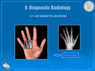
X-Ray Quality Control • Filtration • Focal Spot Size • Collimation • Maximum Fluoroscopic Output • Calibration Verification • Phototimer Performance
Why is Filtration Important? • Tube emits spectrum of x-ray energies • Filtration preferentially attenuates low energy photons • low energy photons expose patients • do not contribute to image • low penetration
Half Value Layer (HVL) • We don’t measure filtration • We measure HVL • HVL: amount of absorber that reduces beam intensity by exactly 50%
kVp HVL (mm Al) 30 0.3 40 0.4 49 0.5 50 1.2 60 1.3 70 1.5 71 2.1 80 2.3 90 2.5 100 2.7 110 3.0 120 3.2 130 3.5 140 3.8 150 4.1 Half Value Layer • Depends upon • kVp • waveform (single/three phase) • inherent filtration • Minimum HVL regulated by law • Maximum HVL regulated only in mammography Georgia State Rules & Regulations for X-Ray
Checking HVL Compliance(Radiographic) • How much aluminum must be placed in beam to reduce intensity by exactly 50%? 90 kVp Measurements; 2.5 mm Al minimum HVL filter mR (mm Al) ------------------- 0 250 2.5 133 filter mR (mm Al) ------------------- 0 250 2.5 125 filter mR (mm Al) ------------------- 0 250 2.5 111 Not OK! Must remove Al to reduce beam to exactly 50% OK! Must add Al to reduce beam to exactly 50% Acceptable HVL > 2.5 mm Marginal HVL = 2.5 mm Unacceptable HVL < 2.5 mm
Checking HVL Compliance(Radiographic) • Is this machine legal? • 2.5 mm Al minimum filtration at 90 kVp 90 kVp Measurements filter mR (mm Al) ------------------- 0 450 2.5 205
Fluoroscopic HVL • Set desired kilovoltage manually • measure exposure rates instead of exposure • Move absorbers into beam as needed
Actual Focal Spot Apparent Focal Spot Focal Spot Size • We measure apparent focal spot • Trade-off • smaller spot reduces geometric unsharpness • larger spot improves heat ratings
Focal Spot Size (cont.) • Focal spot size changes with technique • Standard technique required • 75 kV (typical) • 50% maximum mA for focal spot at kV used • direct exposure (no screen) • NEMA Standardsdefines tolerances Nominal Size Tolerance ------------------------------------- >1.5 mm 30% >0.8 and <=1.5 mm 40% <0.8 mm 50%
Focal Spot Measuring Tools • Direct MeasurementPin Hole Camera • Slit Camera • Indirect Measurement of Resolving Power • Star Test Pattern • Bar Phantom
Direct Focal Spot Measurement • Measure focal spot directly in each direction • Use triangulation to correct for distances • formula corrects for finite tool size • two exposures required for slit Slit Camera Pinhole Camera
Star Test Pattern • Measures resolving power • infers focal spot size • Dependent on focal spot energy distribution • measure • largest blur diameter (in each direction) • magnification • use equation to calculate focal spot size
Bar Phantom • Measures resolving power • Find smallest group where you can count three bars in each direction
Radiographic Collimation • X-Ray / Light Field Alignment • Beam Central Axis • should be in center of x-ray beam • Collimator field size indicators • PBL (automatic collimation) • field automatically limited to size of receptor • Bucky Alignment • Using longitudinal bucky light & transverse detent, x-ray field should be centered on bucky film
X-Ray / Light Field Alignment • Mark light field on table top with pennies
Fluoroscopic Collimation • image field is scale seen on monitor • expose film on table above scale • compare visual field (monitor) with x-ray field on film • must check all magnification modes
Maximum Fluoro Output • put chamber in beam on tabletop • block beam with lead above chamber • fools generator into providing maximum output • 10 R/min. limit for ABS fluoro
CalibrationPerformance Parameters • Timer Accuracy • Repeatability • Linearity/Reciprocity • Kilovoltage accuracy • mA • must be measured invasively
Calibration 120 kVp • mR/mAs should stay constant for all combinations of mA & kVp at any particular kVp mA time mAs mR mR / mAs (msec) ------------------------------------------------------ 100 .1 10 240 24 200 .05 10 ? ? 50 .2 10 ? ? Constant mAs
Calibration 120 kVp • mR/mAs should stay constant for all combinations of mA & time at any particular kVp mA time mAs mR mR / mAs (msec) ----------------------------------------------------- 100 .1 10 240 24 200 .1 20 ? ? 100 .4 40 ? ? Double mAs Double mAs again
Phototiming(check with output or film) • Reproducibility • Density Controls • Field Placement • Field Balance Phototiming Operation should be Predictable
Density Control -2 -1 0 1 2 41 49 62 76 96 Phototimer Density Control Settings R R T a b l e t o p
Phototiming Density Steps should be predictable & approximately even
M e a s u r e m e n t o f P h o t o t i m e r F i e l d P l a c e m e n t / B a l a n c e Lead for checking field placement R R T a b l e t o p Phototimer Field Placement / Balance • Placement • cover desired field with lead • select field as indicated • Balance • no fields covered • select field as indicated
Phototimingchecked with Exposure Index • kV Response • phototimer pick-up attenuation may vary with kV • phototimer must track kV response of rare-earth film • Rate Response • Check with varying • phantom (lucite) thickness • mA
kV Response 4 Optical Density 2 0 70 81 90 kilovoltage kV/Rate Response kV 70 81 90 Lucite 17.5 4.5 4.9 5.2 Depth 12.5 4.7 (cm) 7.5 4.7 Thickness Tracking 4 Density Optical 2 0 17.5 12.5 7.5 Lucite Thickness
The End Any questions, you varmints?