Download
1 / 17
170 likes | 265 Views
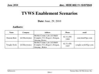
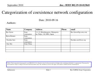
Output power management for TVWS network coexistence. Authors:. Date : 2010-11-08.

E N D
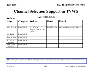
Output power management for TVWS network coexistence Authors: Date: 2010-11-08 Notice:This document has been prepared to assist IEEE 802.19. It is offered as a basis for discussion and is not binding on the contributing individual(s) or organization(s). The material in this document is subject to change in form and content after further study. The contributor(s) reserve(s) the right to add, amend or withdraw material contained herein. Ryo SAWAI, Sony Corporation
Proposed IEEE P802.19.1 service models, mechanisms and its algorithms(*1) on output power managementfor TVWS network coexistence are highlighted here. Introduction Ryo SAWAI, Sony Corporation (*1) The explanation is in section 7.2 of reference [1]
This service provides the maximum output power allocation for TVDBs to protect the incumbent service, such as TV broadcasting and wireless microphone service, from the aggregated interference due to simultaneous transmission of neighbour TVWS networks which are independently operated each other. • The topics on aggregated interference problems from multiple WSD (White Space Device =TVBD)s in-block (= co-channel) and out-of-block (neighbor channel) emission in TVWS operation have been discussed in CEPT SE43[2]. • Also for a TVWS operation where fixed output power level approach in FCC is adopted, the TVBDs shall care about this problem from a viewpoint of incumbent service protection[3]-[5]. Service model #1 Maximum output power allocation service Ryo SAWAI, Sony Corporation
This information service provides the interference power level on each operable TVWS channel for each TVBD. • This interference level information will be helpful for the channel selection for TVWSs. • Because the master TVBD(s) of a TVWS network may be able to find adequate channel(s) from its operable frequency channel(s) without large system overhead due to spectrum sensing deployment, if the master TVBD knows its minimum network requirements such as required link quality, network coverage and so on. Service model #2Information service on aggregated interference power level Ryo SAWAI, Sony Corporation
Basic criterion to specify output power of TVBDs Aggregated mutual interference power in a co-channel operation among TVBDs for target channel # Maximally allowed interference level in a reference point Aggregated mutual interference power in neighbour channel operation among TVBDs for target channel # Interfere-victim Reference point Maximally allowed interference level of broadcasting service receiver Required received signal power of a incumbent service (i.e. broadcasting and wireless microphone and so on) receiver Minimum required SIR (Signal to Interference Ratio) level of incumbent service receiver Ryo SAWAI, Sony Corporation
Parameters (1) Ryo SAWAI, Sony Corporation
Selection criterion of target TVBD(s) • The system may only have to consider (active) master TVBD(s) coordinate each (active) TVWS network in the selection of this target TVBD. • Selection criterion of positioning information of the target master TVBD(s) • The positioning information of the target TVBD may be the one of the closest slave TVBD or virtual slave TVBD in its network coverage area for the protected contour of incumbent service, if the interference signal in the reference point caused by the transmission of the slave TVBD is larger than the interference signal caused by the transmission of the master TVBD according to these transmission parameters. The “virtual” means here that a slave TVBD is assumed to be in the edge of network coverage area of the master TVBD. In these cases, the transmission parameters of the slave TVBD are used for this calculation step, the reference point of the slave node should be each closest point for the protected contour of the incumbent service. • Counting policy of M, N and O • These numbers may count only active TVWS network coordinated by each active master TVBD. Parameters (2) Ryo SAWAI, Sony Corporation
Margin based approach in specifying the maximum output power of TVBDs Calculation methods If the target TVBD uses the same channel as the usage channel(s) of interfere-victim receiver in the reference point If the target TVBD uses the different channel with the usage channel(s) of interfere-victim receiver in the reference point, Parameters Ryo SAWAI, Sony Corporation
Maximized approach of TVWS network capacity in specifying the maximum output power of TVBDs Proposed procedures • Step 0: The parameters for each TVBD to calculate the equation in Slide 5 are input. • Step 1: • Calculation of local specific maximum output power of TVBD(s) without considering • mutual interference effects on in-block/out-of-block interference signal from the other • TVBD(s). The criteria for the calculation are summarized in Appendix (1). • Step 2: • Recalculation of local specific power for each TVBD with the in-block/out-of-block interference • effects from the other TVBD(s), which could be calculated based on the results ( Ptx) of step 1 • for each TVBD, in the following form (7.11) in Appendix (3) • Step 3: • Some interference margin due to the degradation of each may be in the step 2. Therefore, in this • step, the most severe interfere-victim reference point to adjust the maximum output power of • TVBDs is chosen according to the criteria in Equation (7.12) in Appendix (3) • Step 4: • Calculation of output power adjustment value to fulfil the interference margin for each TVBD in • the criteria in Equation (7.13) in Appendix (4) • Step 5: • The final results of local specific maximum output power of TVBDs are calculated in the • Equation (7.15) in Appendix (4). Ryo SAWAI, Sony Corporation
Margin based approach in specifying the maximum output power of TVBDs • Pros.: Easy to calculate • Cons.: Network capacity of each TVWS network permanently decreases, because of its excessive margin setting • Maximized approach of TVWS network capacity in specifying the maximum output power of TVBDs • Pros.: Maximized network capacity of each TVWS network permanently can be obtained • Cons.: Burden for the calculation overhead Pros./cons. Ryo SAWAI, Sony Corporation
Proposed IEEE P802.19.1 service models, mechanisms and its algorithms on output power managementfor TVWS network coexistence were summarized. Conclusions Ryo SAWAI, Sony Corporation
References • [1] “19-10-0145-00-0001-coexistence-mechanism-and-its-algorithm”, IEEE mentor, October 2010 • [2] “Technical and operational requirements for the possible operation of cognitive radio systems in the ‘White Spaces’ of the frequency band 470-790MHz”, DRAFT ECC Report 159, October 2010. • [3] “19-10-0101-00-0001-expectation-for-ieee-p802-19-1-system-from-a-primary-protection-viewpoint”, IEEE mentor, July 2010 • [4] “Second report and order and memorandum option and order”, FCC 08-260, 2008 • [5] “Second memorandum option and order”, FCC 10-174, 2010 Ryo SAWAI, Sony Corporation
Appendix Ryo SAWAI, Sony Corporation
The following four methods are given in equations (7.5) – (7.10), • #1: Equal transmission power distribution method, • #2: Path-loss based/Unequal transmission power distribution method, • #3: Extension of the former two methods using the SM (Safety Margin) value, which will be caused by the interference power level estimation errors in master TVBD of each TVBD network, and • #4: Network prioritized method of the former two approaches. Appendix (1)Criteria using in step 1 Ryo SAWAI, Sony Corporation
Appendix (2)Equations #1: Equation (7.5) #2: Equation (7.6) #3: Equation (7.7) #4: Equation (7.8) shows the weight TVBD# Ryo SAWAI, Sony Corporation
Appendix (3)Equations Equation (7.11) Equation (7.11) Equation (7.12) Ryo SAWAI, Sony Corporation
Appendix (4)Equations Equation (7.13) Equation (7.14) Equation (7.15) Ryo SAWAI, Sony Corporation