Download
1 / 36
360 likes | 520 Views
RTML Design and Rational for ILC Nikolay Solyak Fermilab. CLIC 08 workshop, CERN, Oct. 14-17, 2008. Outline RTML Optic Design (RDR) Technical Systems Emittance control Post-RDR changes. RTML Functions. Transport Beam from DR to ML Match Geometry/Optics Collimate Halo

E N D
RTML Design and Rational for ILCNikolay SolyakFermilab CLIC 08 workshop, CERN, Oct. 14-17, 2008 CLIC 08, CERN, Oct. 14-17, 2008
Outline • RTML Optic Design (RDR) • Technical Systems • Emittance control • Post-RDR changes CLIC 08, CERN, Oct. 14-17, 2008
RTML Functions • Transport Beam from DR to ML • Match Geometry/Optics • Collimate Halo • Rotate Spin • Compress Bunch (6mm0.3mm) • Preserve Emittance - Budget for Vert.norm. emittance < 4nm • Protect Machine • 3 Tune-up / MPS abort dumps • Additional constraints: • Share the tunnel with e-/e+ injectors • Need to keep geometries synchronized CLIC 08, CERN, Oct. 14-17, 2008
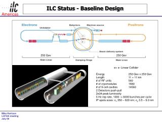
RTML Schematic (RDR) Areas, where tunnel length saving is essential BDS Same curved tunnel (RTML/ML) Separate tunnel 1254 m Note: e- and e+ RTMLs have minor differences in Return line (undulator in e- linac side) and Escalator (DR’s at different elevations); they are otherwise identical. CLIC 08, CERN, Oct. 14-17, 2008
Optics Design (RDR) Horizontal plane • Horizontal Arc out of DR ~km straight • In injector tunnel • “Escalator” ~0.6 km vertical dogleg down to linac tunnel • Return line, weak FODO lattice • In linac tunnel • Vertically curved • Vertical and horizontal doglegs • Turnaround • 8° arc in spin rotators • BCs are net straight Vertical plane DRX+ arc Horizontal plane DR-RTML hand-off point defined extraction point where η,η’ 0 RTML mostly defined by need to follow LTR geometry Stay in same tunnel Design is OK at conceptual level DRX connection CLIC 08, CERN, Oct. 14-17, 2008
DR connection (RDR) • Both sides need 5GeV SC linacs (e+/e- sources); • e+ side also needs KAS and e+ transfer line from undulator • Post RDR modifications • No elevation for the service tunnel • ML and RTML tunnels merge in horizontal plane • New DR design • Shorter tunnel shared with KAS ? CLIC 08, CERN, Oct. 14-17, 2008
DRX Connection (2) • Current design is entirely planar (horizontal plane) • DRs are in different planes • Sources need cryomodules and SC solenoids • Big heavy objects which want to sit on the floor • Working agreement between sources, DR, RTML, CFS: • CMs and SC solenoids always sit on floor • RTML hangs from source tunnel ceiling at same location as in linac tunnel DR Tunnel – 1.44 m Vertical separation e+ DR tunnel e- e+ RTML e- RTML e+ e+ src e- src e- ML Tunnel - 2.14 m Vert. beam separation CLIC 08, CERN, Oct. 14-17, 2008
“Getaway” Straight (or “DR Stretch”) • About 1.1 km long • Has two parts • “Low-beta” region with decoupling and emittance measurement • “High-beta” region with collimation system • Includes PPS stoppers • For segmentation • Good conceptual design • Need to match exact required system lengths • Beta match between low- and high-beta optics not great • Length of “Getaway’’ can be minimized to ~ 500m Beam collimation Energy collimation Decoupling: Skew correctors Diagnostics: Emittance meas CLIC 08, CERN, Oct. 14-17, 2008
Escalator • Vertical dogleg • Descends 7.85 meters over ~590 m • Uses 2 vertical arcs separated by weak FODO lattice • Good conceptual design • Uses Keil-style eta matching • Beta match between “strong” and “weak” lattices not great • Escalator-linac tunnel connection does not match CFS design • Need to make match according CFS design • Shorter length for smaller vertical separation of the DR and ML tunnels and larger slope, min ~200-300 m CLIC 08, CERN, Oct. 14-17, 2008
Return Line e- Return e- ML Undulator 400 MeV e+ • Weak FODO lattice at ML ceiling elevation (1Q/~36m), XYcorr+BPM • Vertically curved tunnel thru ML area Dispersion matching via dipole correctors • Laser-straight tunnel thru BC area • Electron line ~1.2 km longer than positron Goes thru undulator area • Electron Return line and positron transfer line need to be exchanged CLIC 08, CERN, Oct. 14-17, 2008
Turnaround (D & B) • Actually does 3 jobs • Turns the beam around • Note: need to bend away from service tunnel • Brings beam down from ceiling to linac elevation (near floor) • Vertical dogleg • Adjusts x position to meet linac line • Horizontal dogleg • Order: H dogleg, V dogleg, turnaround • Risk - high packing area ~90% magnets. Tunnel length is already min. Horizontal Spin Rotator Vertical CLIC 08, CERN, Oct. 14-17, 2008
Spin Rotation • Design based on Emma’s from NLC ZDR. Arbitrary spin orientation in IP • 2 solenoids with Emma rotator between them • Rotate spin 90° in xy plane while cancelling coupling • 8° arc • Rotate spin 90° in xz plane • Another 2 solenoids + Emma rotator • Basic design seems sound • Very small loss in polarization from vertical bending in linac tunnel CLIC 08, CERN, Oct. 14-17, 2008
ILC Baseline Bunch Compressor • Longitudinal emittance out of DR: • 6mm (or 9 mm) RMS length • 0.15% RMS energy spread • Want to go down to 0.2-0.3 mm • Need some adjustability • Use 2-stage BC to limit max energy spread • 1st: Compress to 1 mm at 5 GeV • 2nd: Accelerate to 15 GeV and Compress to final bunch length • Both stages use 6-cell lattice with quads and bends to achieve momentum compaction (wiggler) • Magnet aperture ~ 40cm • Total Length ~1100 m (incl. matching and beam extraction lines) • Minimum design is possible if assume compression 60.3 mm only • Shorter 2-stage BC • Or short single-stage BC • Cheaper magnets RF1 RF2 Wiggler 1 Wiggler 2 One wiggler cell RF system • BC1: 3 CMs with quads (+spare kly) • BC2: 14 RFunits (3CM’s each)+1spare • Total 48 CM’s per side CLIC 08, CERN, Oct. 14-17, 2008
BC: Phase and amplitude stability The required tolerances for amplitude and phase stability in BC are very tough: • - Phase stability tolerance: 0.25°/0.16° – long/short bunch • - Amplitude stability tolerance: 0.5%/0.35% rms – long/short bunch • Bunch compressor RF cavities operate close to zero-crossing: • Phase 105° off-crest (BC1) • Phase 27.6° off-crest (BC2) • The gradient in the RF system ~30 MeV/m. Zero crossing regime – complication for LLRF system. • Study of the phase and amplitude stability of the RF system @ FLASH (2009). CLIC 08, CERN, Oct. 14-17, 2008
Alternative Bunch Compressor • An alternate bunch compressor design exists (~700m) • 6-cell wigglers (~150 m each, 102 bend magnets) replaced by chicanes (~40 m each, 4 bend magnets) • Advantages: Shorter, Simpler, Cheaper (less magnets) • Disadvantages: Big x offset from straight line (~1.8 m) • Doesn’t have natural locations for dispersion tuning quads • Length Saving: ~ (200 ÷ 300 m) CLIC 08, CERN, Oct. 14-17, 2008
Pulsed Extraction Lines • 3 Extraction Lines in each RTML side for emergency beam abort (MPS) and tune-up • EL1 - after DR exit, diagnostics, global correction • 5 GeV, E = 0.15% • Keep DRs running @ full power during access • Keep DRs and extraction tuned during access • MPS abort (~100ns) • ELBC1 - after BC1 • 5 or 4.88 GeV, E = 0.15% and 2.5% • Tune up BC1 without beam in BC2 • MPS abort • ELBC2 - after BC2 • 15 GeV, E = 0.15% and 1.8% • Tune up BC2 without beam in linac • MPS abort • All have 220 kW beam handling power • Full power for DRX, BC1 • 1/3 power for BC2 CLIC 08, CERN, Oct. 14-17, 2008
Extraction Line Layout Note: Schematic only, not to scale! ~ 30 - 40 m Beam dump: 220kW @15GeV + local shielding Beamline to tune-up dump 5 m >2 m earth shielding Accelerator Tunnel <~100W Beam loss this area Kicker and septum 20-cm-thick Pb 3 burn through monitors Access OK Main beamline (DR-to-IP) 1 km 5 m earth shielding Service Tunnel Access OK: 0.14 mSv/hr w/o local dump shielding; 0.025 mSv/hr with local dump shielding CLIC 08, CERN, Oct. 14-17, 2008
EL1 design CLIC 08, CERN, Oct. 14-17, 2008
ELBC1 Line Design match septum DBA Defocus • Separation of the two lines at CM location (14m down) - 2m; • Separation of the dump and the ML ~5 m; • DBA to decouple dispersion and beam size issues • Beam size on the dump window ~15 mm2 • Length = 20.7 m 0.15% energy spread 2.5% energy spread • Two collimators to protect downstream triplet • intercepts 3.9 kW/train and 18.8 kW/train CLIC 08, CERN, Oct. 14-17, 2008
ELBC2 Design Defocus • ELBC2 similar to ELBC1, but ~ 5m longer (extra bending cell) • 6 septum+6 bends+12 quads, • two collimators: 5.2 kW (protect quads) and 14.1 kW (dump window) 0.15% (green)and 1.8% (red) energy spread CLIC 08, CERN, Oct. 14-17, 2008
Halo and Energy Collimation • ILC specification: • Needs to limit halo at end linac to ~10-5 of total beam power • Halo Collimation after DR • BDS specification as requirement • Halo power ~ 220 W • Provide machine protection • Collimators stop out-of-control beam from DR • Need to keep out-of-control beam from frying collimators, too! • Energy collimators after betatron collimation system • Scattered particles • Off-momentum particles / bunches from DR • Additional energy collimators • In BC1 wiggler • In BC2 wiggler • Collimators in Extraction Lines ELBC1 and ELBC2 • Need to understand machine protection issues for these collimators CLIC 08, CERN, Oct. 14-17, 2008
Technical Systems • Magnets and power supplies (~4600 Magnets) • SC quads/correctors/solenoids (36/54/8), • RT quad, correctors, septa • Pulsed magnets, kickers, bends, FB/FF correctors • Vacuum system • Current baseline • 2 cm OD stainless chambers • Exceptions: BC bends, extraction lines, CMs • 20 nTorr in long line from DR to turnaround • Passivated to reduce outgassing rate • 100 nTorr in balance of system (turnaround to linac) • Dumps and Collimators • 3 dumps per side with 220 kW capacity • Betatron and energy spoilers / absorbers with ~200 W capacity (20 adjustable aperture (5W) +28 fixed-aperture collimators)/side • Few collimators with ~10 kW capacity CLIC 08, CERN, Oct. 14-17, 2008
Six ~220kW Aluminum Ball Dumps 50cm Diameter x 2m long Aluminum Ball Dump with Local Shielding RW 50kW 3-loop 2006 Rad Water Cooling for ISIS Neutron Spallation Targets Cost ($1M each) is dominated by: • 3-loop radioactive water processing system • The CFS infrastructure, shielding, etc. Similar dumps in use at SLAC CLIC 08, CERN, Oct. 14-17, 2008
Technical Systems (2) • Instrumentation • BPM’s at every quad, plus high dispersion points in wigglers • Serve a number of functions: feedback, feed-forward, beam-based alignment and steering, energy diagnostic • room-temp C- or L-band (BC2 upstream) cavity BPM’s • 3 suites of Laser Wires (LW) in each RTML • 4 wires per suite, set up for 2D emittance measurement • Bunch length measurement • LOLA (3.9 GHz) + screens in each BC • Possibly EO monitors (not in RDR baseline) • SLMO’s (Synchrotron Light monitor) in BC wigglers for energy spread measurement (4) • 3 dedicated phase monitors per side • Toroids, 4 ion chambers and 150 photomultipliers (MPS) CLIC 08, CERN, Oct. 14-17, 2008
Technical Systems (3) • 1.3 GHz SC RF system plus supporting utilities • 48 CMs per side (1 RF source per 3 CMs, as in ML) • 3 CM x “8Q” in BC1 • 15 RFunits x “9-8Q-9” in BC2 • BC1: 2nd source with RF switch for redundancy • LLRF issues • Phase stability • Beam loading compensation • Beam loads RF at decelerating phase • Unlike ML, need to “jump” both amplitude and phase of RF source @ beam time • Cryo system (~6.5% cost of ML Cryo system) • Part of ML cryogenic system • Also supports SC solenoids in spin rotator • BC’s are laser-straight • Probably OK – only ~1 km long CLIC 08, CERN, Oct. 14-17, 2008
Sources of emittance degradation • Synchrotron radiation • From DRX arc, turnaround, BC wigglers • Beam-ion instabilities • Beam jitter • From DR • From stray fields • Dispersion • DR extraction • Misaligned quads • Rolled bends • Coupling • DR extraction septum • Rolled quads • Misaligned bends • Quad strength errors in spin rotator • Pitched RF cavities • Produce time-varying vertical kick • RF phase jitter • Varies IP arrival time of beams • Beam halo formation • Collimator and cavity Wakefields • Space charge • Resistive wall wakes in vac. chamber • LET BBA @ ILC RTML • Several BBA used: • Ballistic Alignment (BA) • Kick minimization (KM) • Dispersion Free Steering • Dispersion Bumps • 4D Coupling Correction • Adaptive alignment • Wakefield Bumps • Feed-Back and • Feed Forward system CLIC 08, CERN, Oct. 14-17, 2008
Survey Alignment CLIC 08, CERN, Oct. 14-17, 2008
Static tuning in part of RTML (upstream BC1) COLL2 Turnaround Spin rotator SKEW EMIT2 EMIT collimator Skew CLIC 08, CERN, Oct. 14-17, 2008
Emittance budget (factor ~2 larger) CLIC 08, CERN, Oct. 14-17, 2008
Cost and its Distribution • CFS + BC RF system = 68% of costs • Correlated – much of CFS cost is housing for BC cryomodules • Remainder dominated by RT beam transport • Quads, correctors, BPMs, vacuum system • Small amount of “exotica” • Non-BPM instrumentation, controls, dumps, collimators CLIC 08, CERN, Oct. 14-17, 2008
ILC Damping Ring – New Design 300 m Injection Injection Extraction Extraction • New ILC DR lattice is shorter. • Bunch length = 6 mm • In old RDR design: • 9 mm (easy) • 6 mm (more challenge) • Energy spread = 0.15% • New DR increases the length of the RTML linac in each side (e+ and e-) of ~300 m, but not CFS • Need redesign/adjust DRX lattice to accommodate changes in DR Layout of the ILC Damping Ring blue - old RDR (2007); red - new DCO (Feb.2008) CLIC 08, CERN, Oct. 14-17, 2008
Possible configuration of the RTML/source tunnels DR 6 m BDS ML DR ~500 m ~100 m ~100 m ~ 500 m 500 m KAS RTML/e+ RTML/e- Service Tunnel RTML/e+ RTML BDS ML ML 300 m Discussion at Dubna ILC workshop, June, 2008 Minimum length of separate RTML/source tunnel • Smaller vertical separation DR/BDS tunnel: 10m 6 m • Length constrains: • Electron source side (straight) ~ 500 m • Positron source: 950m=500(KAS)+450m(SCL/TRL) • RTML tunnel length ~ 900 m (now ~1250 m) Possible tunnel saving ~ (600-700) m /side CLIC 08, CERN, Oct. 14-17, 2008
Short Single stage BC (Eun-San Kim)-2006 • Compress 6mm 0.3mm only • Acceleration 4.515 GeV will require 15 RFunits (incl. 1 spare) ~ 600 m • Energy spread @ 15 GeV 3.5%*(4.5/15) ~ 1% • BC length ~700m. Saving ~ 1100-700 = ~ 400m • No ELBC2 extraction line • Disadvantages: No flexibility, tunability, larger emittance growth ??? CLIC 08, CERN, Oct. 14-17, 2008
Single-stage BC (PT, TOR, AW) - 2005 • Input beam parameters • Energy = 5 GeV • Energy spread= 0.15% • Bunch length = 9 mm (In new DR design bunch length = 6mm) • Single –stage BC: • In case 60.3mm energy spread ~ 4 % • Acceleration from 4.615 GeV will reduce energy spread by factor of ~3 • BC length ~340m, post-acceleration ~600m, Saving 1100-940 = ~ 160m • Disadvantages (compare to 2-stage BC): • - Low flexibility and tunability, emittance growth ??? CLIC 08, CERN, Oct. 14-17, 2008
Further RTML work • Study Possible Cost saving options: • Minimize length of RTML/source tunnel • Alternative 2-stage or 1-stage bunch compressor • Reduce pulsed extraction Lines from 3 per side to 2 per side • Lattice design aand emittance studies • Re-evaluate/match geometry and optics to accommodate DR changes, CFS req’s and cost saving options • Demonstrate require emittance budget for Static tuning • Dynamic tuning (ground motion, jitter, AC magnetic fields, etc) • Design FB/FF system • Design/prototyping critical components CLIC 08, CERN, Oct. 14-17, 2008
Acknowledgements RTML team: SLAC, FNAL, ANL, LBL, Cornell Univ., KEK, DESY, INFN, CERN, KNU/Korea, UBC, IHEP/China Design and Performance:P. Tenenbaum, J. Smith, S. Molloy, M. Woodley, S. Seletskyi, E.-S. Kim, D.Schulte, A. Latina, K. Kubo, M. Church, L. Wang, P. Spenzouris, M. Venturini, I. Reichel, J.Gao… Engineering and Civil:V. Kashikhin, P.Bellomo,T.Mattison ,Y.Suetsugu,J. Noonan, X.Qiong, P.Michelato, T.Markiewicz, R.Larsen, M.Wendt, John Carwardine, C.Saunders, T.Peterson, F.Asiri, J.-L Baldy, G.Aarons, T.Lackowski, … CLIC 08, CERN, Oct. 14-17, 2008