ZTF Cryostat Finite Element Analysis
250 likes | 473 Views
ZTF Cryostat Finite Element Analysis. Andrew Lambert 2013-02-01. Outline. Fused Silica Window – Case XV Aluminum Focal Plate Assembly Single CCD Assembly G10 Flex Supports. Fused Silica Window Mesh and BCs. Quarter model simulated due to symmetry – Case XV Boundary conditions

ZTF Cryostat Finite Element Analysis
E N D
Presentation Transcript
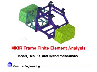
ZTF Technical Meeting ZTF Cryostat Finite Element Analysis Andrew Lambert 2013-02-01
Outline ZTF Technical Meeting • Fused Silica Window – Case XV • Aluminum Focal Plate Assembly • Single CCD Assembly • G10 Flex Supports
Fused Silica Window Mesh and BCs ZTF Technical Meeting • Quarter model simulated due to symmetry – Case XV • Boundary conditions • Simply supported at O-rings • Radiation to ambient temperature • Radiation to cold CCD temperatures • Vacuum loading • Worst case temperature loading, however stress is dominated by vacuum loading, not temperature
Fused Silica Window Temperatures ZTF Technical Meeting • Temperature contours show that the thermal gradient is approximately 6 oC • Heating occurs due to ambient radiation • Due to high emissivity of the fused silica (~0.93), the window represents a major heat leak to the CCD array and aluminum focal plate
Fused Silica Window Max Stress ZTF Technical Meeting • Evaluation of the maximum principle stress • Glass fails in tension, thus must evaluate max. tensile stress • Maximum stress occurs at center of the window ~6.5 MPa • High stress around support edge are artificially high due to simulation BC’s • Care should be taken however -> angle the inside support wall to avoid glass to metal contact
Fused Silica Window Deflection ZTF Technical Meeting • Maximum deflection in the normal direction is ~12.4 microns • Occurs at window center and gradually decrease towards the support edges • Very large improvement over initial design without increasing window thickness
Fused Silica Window MOS and FOS ZTF Technical Meeting • LBNL specifies a factor of safety = 8 • Current design satisfies this criteria • MOS = 0.23 -> May experience a 23% load increase before exceeding acceptable levels • To protect against cryogen leakage, a 11.5 psig burst disk will be installed on back of dewar assembly • Simulation of this internal positive pressure shows that for this condition FOS remains > 8
Focal Plate Assembly ZTF Technical Meeting • Previous to this design, rigorous analysis of different focal plate material choices was accomplished • Silicon Carbide • Invar • Aluminum • Studies showed that aluminum was a viable material for use • Good thermal performance • Less expensive • Machine-ability • Aluminum focal plate design has been through several iterations prior to its current state • Increased thickness to reduce bending • Thinner flexures to allow for differential thermal contraction • Pockets to reduce the overall mass while maintaining heat paths
Focal Plate Assembly ZTF Technical Meeting Focal Plate Flatteners and Detectors Dewar G10 Flex Support
Assembly Mesh and BCs ZTF Technical Meeting • Focal plate thermal simulation yields assembly temperature profiles • Boundary conditions • Radiation to ambient on contact lens surface • Radiation to cold CCD on contact lens back • Radiation to warmer contact lens on CCD surface • Set cold temperature of -130 oC for thermal links on back of Al plate • Ambient temperature on outside of dewar frame
Assembly Temperatures ZTF Technical Meeting • Assembly temperatures show that the contact lens temperatures are well above the focal plate temperatures • In the -30 oC to -60 oC range • Also, the dewar can temperature is successfully isolated from the aluminum plate by the G10 supports • The heat removed through the thermal link attach points it approximately 35 Watts, with 17.5 Watts to each cryocooler
Aluminum Focal Plate Temperatures ZTF Technical Meeting • High thermal conductivity of aluminum enhances cooling performance • Even down to low temperatures ~ -130 oC • Temperature gradient across the focal plate of ~ 8 oC • Less expensive than other material and more machine-able • Due to high thermal contraction, addition of support flexures are need to accommodate thermal shrinkage
CCD Temperatures ZTF Technical Meeting • Prime interest point is thermal gradient across the CCD array • Across all 12 CCD’s there is 3 oC temperature difference • Temperature gradient across a single CCD is less than a degree
Contact Lens and Frame Temperatures ZTF Technical Meeting • Contact lens and frame are insulated from the CCD using G10 washers • Provides an effective barrier for heat transfer from the contact lens to the CCD array • Maximum lens temperature is -31oC, with a minimum of -60 oC • Approximately 30 oC temperature gradient across lens
Assembly Deformation ZTF Technical Meeting • Aluminum focal plate assembly experiences shrinkage due to low temperature operation • Various materials are used • Material selection has been optimized for best CTE performance • Reduce CCD deflection • At -130 oC, α = 1.6e-5 • Using the analytical formula to the lower right, contraction is +/-550 microns in x & y; +/-49 microns in z • Agrees well with FEA result
CCD Deflection ZTF Technical Meeting • CCD deflection is reduced by Invar spacers between the CCD and aluminum plate • CCDs at the center of the array experience the greatest deflection
Detector Surface Deflection ZTF Technical Meeting • Detector surface deflection is due to thermal shrinkage • Maximum deflection at the center of the array • Deflection ranges from -90 to -105 microns in the direction normal to the detector surface • Peak to peak deflection change is 15 microns
Single CCD Assembly ZTF Technical Meeting • Single CCD assembly used to examine stress in the aluminum flexures • Small model allows easier examination of critical components and reduces solution time • Boundary conditions are applied to mimic the same behavior as the overall plate assembly Flattener CCD and Detector Invar Frame Focal Plate
Single CCD Temperatures ZTF Technical Meeting • Temperatures mimic those found in full plate simulation almost exactly • Means contraction is similar and thus flexure stress can be evaluated • Model includes every component found in the CCD assembly
Aluminum Flexure Stress ZTF Technical Meeting • Aluminum flexure stress occurs due to differential in expansion from CCD to aluminum base • Maximum equivalent stress in the flexure of about 35 MPa, which is well below yield ~ 260 MPa • Thin flexure allows bending • Due to aluminum’s larger CTE as compared with the SiC detector • Because stress is well below yield, deformation is elastic and aluminum should return to normal shape when unstressed
G10 Support Temperatures ZTF Technical Meeting • G10 supports are used to hold the focal plate in place as well as insulate it from ambient temperatures • Connected to warm end at 22 oC and cold plate at -125 oC • Show large temperature gradient across the support
G10 Support Deformation ZTF Technical Meeting • Support deforms due to several loads • Aluminum plate contraction • G10 support shrinkage • Gravitational loading • Maximum deflection at the focal plate support point of 620 microns • Must examine stresses due to thermal contraction
G10 Support Stress ZTF Technical Meeting • Equivalent stress in MPa shows maximum stress near support locations • Max stress is in the 25-35 MPa range • 35 MPa stress is a localized concentration and is most likely artificial • Yield strength of ~220 MPa • Notice that dewar support point on left is allowed to slide • Reduces stresses from contraction
Future Work ZTF Technical Meeting • Integrate thermal shield • Dewar structure optimization for vacuum load • Back wall optimization for stiffness • Safety criteria forflatteners • Examination of titanium for flex support material • Thermal linkage heat transfer