Download
1 / 17
170 likes | 401 Views
Sequence of QC steps for main bus bar splices. Control of cables and stabiliser prior to connection by ICIT team. Temperature control during soldering, visual inspection of the finished splice by operators. QC visual and geometric inspection according to IEG-C-BR-001 rev C. QC US test.

E N D
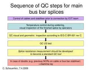
Sequence of QC steps for main bus bar splices Control of cables and stabiliser prior to connection by ICIT team Temperature control during soldering, visual inspection of the finished splice by operators QC visual and geometric inspection according to IEG-C-BR-001 rev C QC US test Splice resistance measurement should be developed to become a standard QC tool In case of doubts (e.g. previous NCRs on cable or bus bar stabiliser) Gamma ray C. Scheuerlein, 7.4.2009
Example QC of QBBI.B25R3 • Produced the 17.3.2009. Special U-piece (-1 mm length) used for M3-corridor. OK • Visual and geometric inspection by QC team according to IEG-C-BR-001 rev C, the 18.3.2009. OK • US-test 4 out of 4 US signals OK for all splices. • Splice thickness OK. • NCR 993939 was opened and gamma ray examination was requested for QBBI.B25R3-M3-cryoline, because room temperature splice resistance of 12.4 μΩ is higher than average values. C. Scheuerlein, 7.4.2009
Resistance results QBBI.B25R3-M3-cryoline • The higher resistance is at the lyra side of QBBI.B25R3-M3-cryoline (7.60.1 μΩ and 5.90.2 μΩ for lyra and connection side, respectively (distance between voltage taps=8.5 cm)). • Resistance result is influenced by position of voltage taps (e.g. 11.90.5 μΩ and 12.6 0.2 μΩ for measurements on top or on the side of splice, respectively (distance between voltage taps=17 cm)). C. Scheuerlein, 7.4.2009
Photos QBBI.B25R3-M3-cryoline QBBI.B25R3-M3-cryoline side view top view bottom view QBBI.B25R3-M3-cryoline-lyra-side (R= 7.60.1 μΩ) C. Scheuerlein, 7.4.2009
Gamma rays QBBI.B25R3-M3 QBBI-B25R3-M3-QRL-connection QBBI-B25R3-M3QRL-lyra (7.60.1 μΩ) QBBI-B25R3-M3Cor-cC QBBI-B25R3-M3-Cor-lyra QBBI-B25R3-M3-Cor-connection C. Scheuerlein, 7.4.2009
US test result QBBI.B25R3-M3-cryoline • For all splices tested so far during the 2009 shutdown we found 4 out of 4 good US signals. C. Scheuerlein, 7.4.2009
Temperature cycle QBBI.B25R3-M3-cryoline C. Scheuerlein, 7.4.2009
QQBI.29R3-M1-corridor • NCR 993937, splice resistance above average values. • The cable and bus bar stabiliser of SSS 221 were damaged in SMA18. • Visual and geometrical control result is acceptable. • Because of the stabiliser deformation prior to soldering, a perfect splice could not be achieved. Therefore, we asked for resistance measurement and gamma ray images. • Splice resistance is with 19.2 μΩ somewhat higher than average values. QQBI.29R3-M1-corridor C. Scheuerlein, 7.4.2009
QQBI-29R3-M1-Cor-Co QQBI-29R3-M1-Cor-Ly QQBI-29R3-M1-QRL-Co QQBI-29R3-M1-QRL-Ly QQBI.29R3-M1 gamma ray images C. Scheuerlein, 7.4.2009
NCRs for QBBI.A32R3 • NCR 994206 for M3-cryoline gap with an approximate macroscopic transverse cross section of 20 mm2. Splice resistance measured by TE-MPE team =10.7 μΩ, which is not significantly higher than average. • NCR 993950 for M1-cryoline because of comparatively high splice resistance (20.3 μΩ). • Resistance of M2-corridor=19.6 μΩ (always with a distance of 17 cm between voltage taps). C. Scheuerlein, 7.4.2009
Photos QBBI.A32R3 • Visual and geometric inspection by QC team according to IEG-C-BR-001 rev C. M1 and M2 OK QBBI.A32R3_M1 QBBI.A32R3_M2 QBBI.A32R3_M1 QBBI.A32R3_M1 C. Scheuerlein, 7.4.2009
QBBI.A32R3 resistance results • QBBI.A32R3-M1-cryoline • Total 19.70.3 μΩ (over 17 cm) • connection side-10.0 0.1 μΩ (8.5 cm) • lyra side-12.7 0.4 μΩ (8.5 cm) • QBBI.A32R3-M2-cryoline • Total 21.30.1 μΩ (over 17 cm) • connection side-12.00.5 μΩ (8.5 cm) • lyra side-10.80.2 μΩ (8.5 cm) • Influence of the voltage tap position on M1 and M2 splices (e.g. QBBI.A32R3-M2-corridor resistance =21.30.1 μΩ and 20.60.6 μΩ as measured with voltage taps at the side and on top of the splice, respectively). C. Scheuerlein, 7.4.2009
Gamma rays QBBI.A32R3 QBBI-A32R3-M1QRL-cL 12.7 0.4 μΩ QBBI-A32R3-M1QRL-cC 10.0 0.1 μΩ QBBI-A32R3-M2QRL-cC QBBI-A32R3-M2QRL-cL
Splice resistance measurement as QC tool • The room temperature splice resistance measurement is the only functional quality control that can be performed in-situ. Resistance measurements from TE-MPE team have demonstrated that comparative splice resistance values can be obtained. • Visual inspection can only detect macroscopic gaps on the outside of the splice. • Therefore, a comparative splice resistance measurement should be performed on all splices. A procedure should be defined so that we all measure in the same way. • We need threshold values for acceptable and not acceptable resistance values for M1 and M3 splices, taking into account the limitations of the resistance measurement set-up (short distance between current source and voltage taps). C. Scheuerlein, 7.4.2009
Example NCR 993403 concerning splice thickness • NCR LHC-MSC-QBBI.A27R3-sur M1 coté corridor, coté gauche, epaisseur plus importante qu'habituellement de la connexion. • A second cycle was performed without disconecting the splice. Thickness was reduced from 11.4 mm to 10.9 mm. Room temperature splice resistance 17.6 μΩaverage value. X-rays taken. NCR closed with warning. QBBI.A27R3-M1-corridor-lyra X-ray images taken after 2nd cycle QBBI.A27R3-M1-corridor-lyra QBBI.A27R3-M1-corridor-connection C. Scheuerlein, 7.4.2009
Quality control of line N and line M US welds • Visual and geometrical inspection according to standard procedures IEG-C-US-001 RevC “Controle visuel des soudures US sur les bus bars auxiliaires des lignes M1 et M2” and IEG-C-US-002 “Controle visuel des soudures US de type N”. • On-line analysis of production data (weld duration) by operators (not an acceptance criterion). • Production data is saved on dfs. • Photos of all US welds are saved on dfs. C. Scheuerlein, 7.4.2009
Qualification of US welding and inductive soldering machines • US4, US5 and US6 qualified for line N spool welds (round strand) with 0.80 mm compression (enfoncement). • US1, US2, US3, US7 qualified for line M spool welds (rectangular strand) with 0.68 mm compression. • BR2, BR3, BR5, BR7 qaulified for main bus bar soldering. • Qualification results can be found under: \\cern.ch\dfs\Workspaces\s\Sector81Interconnect\Shutdown2009\Quality-Control\Electrical-Connections\Rc-results-tensile-tests C. Scheuerlein, 7.4.2009