Download
1 / 22
220 likes | 379 Views
Muon Front Ends. Providing High-Intensity, Low-Emittance Muon Beams for the Neutrino Factory and Muon Collider. Contents. Future Accelerator Projects Requiring Muon Front Ends Neutrino Factory Muon Collider Choice of Particle – why Muons? Design Components and Options

E N D
Muon Front Ends Providing High-Intensity, Low-Emittance Muon Beams for the Neutrino Factory and Muon Collider Stephen Brooks / RAL / April 2004
Contents • Future Accelerator Projects Requiring Muon Front Ends • Neutrino Factory • Muon Collider • Choice of Particle – why Muons? • Design Components and Options • Research Currently Underway • By both Grahame Rees and myself Stephen Brooks / RAL / April 2004
The Neutrino Factory • Goal: To fire a focussed beam of neutrinos through the interior of the Earth • What’s the point? • Constrains post-Standard Model physics • But why does this involve muons? • Neutrinos appear only as decay products • Decaying an intense, high-speed beam of muons produces collimated neutrinos Stephen Brooks / RAL / April 2004
The Neutrino Factory • p+ p+ m+ e+nenm • Uses 4-5MW proton driver • Could be based on ISIS Stephen Brooks / RAL / April 2004
The Muon Collider • Goal: to push the energy frontier in the lepton sector after the linear collider • p+ p+,p− m+,m− m+ m- 3+3TeV Muon Collider Ring Stephen Brooks / RAL / April 2004
Why Collide Muons? Stephen Brooks / RAL / April 2004
Design Challenges • Must accelerate muons quickly, before they decay • Synchrotron acceleration is too slow • But once g is high, you have more time • High emittance of pions from the target • Use an accelerator with a really big aperture? • Or try beam cooling (emittance reduction) • In reality, do some of both Stephen Brooks / RAL / April 2004
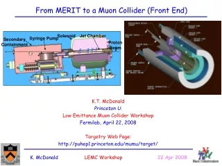
Muon Front End Components • Targetry, produces pions (p±) • Pion to muon decay channel • Uses a series of wide-bore solenoids • “Phase rotation” systems • Aim for either low DE or short bunch length • Muon ionisation cooling (as in “MICE”) • Expensive components, re-use in cooling ring • Muon acceleration (RLAs vs. FFAGs) Stephen Brooks / RAL / April 2004
The Decay Channel • Has to deal with the “beam” coming from the pion source • Pion half-life is 18ns or 12m at 200MeV • So make the decay channel about 30m long • Grahame designed an initial version • Used S/C solenoids to get a large aperture and high field (3T mostly, 20T around target) • Needed a better tracking code… Stephen Brooks / RAL / April 2004
The Decay Channel (ctd.) • Developed a more accurate code • Used it to validate Grahame’s design… • 3.1% of the pions/muons were captured • …and parameter search for the optimum • Within constraints: <4T field, >0.5m drifts, etc. • Increased transmission to 9.6% • Increased in the older code (PARMILA) too • Fixed a problem in the original design! Stephen Brooks / RAL / April 2004
Two Phase Rotation Options • Chicane (2001) • FFAG-style magnets • Shortens the bunch • Have optimised matching • 2.4% net transmission • No cooling? • 31.4MHz RF (2003) • Reduces the energy spread • 180±75MeV to ±23MeV • Feeds into cooling ring Stephen Brooks / RAL / April 2004
RAL Design for Cooling Ring • 10-20 turns • Uses H2(l) or graphite absorbers • Cooling in all 3 planes • 16% emittance loss per turn (probably) • Tracking and optimisation later this year… Stephen Brooks / RAL / April 2004
Web report BACKUP! In case the time is longer than my slides. Stephen Brooks / RAL / April 2004
Muon Acceleration Options • Accelerators must have a large aperture • Few turns (or linear) in low energy part, so muons don’t decay • Recirculating Linacs (RLAs, studied first) • FFAGs (cyclotron-like devices) • Grahame is playing with isochronous ones Stephen Brooks / RAL / April 2004
NuFact Intensity Goals • “Success” is 1021m+/yr in the storage ring Stephen Brooks / RAL / April 2004
Tracking & Optimisation System • Distributed Computing • ~450GHz of processing power • Can test millions of designs • Genetic Algorithms • Optimisation good up to 137 parameters… • Accelerator design-range specification language • Includes “C” interpreter Stephen Brooks / RAL / April 2004
The Decay Channel • Has to deal with the “beam” coming from the pion source Evolution of pions from 2.2GeV proton beam on tantalum rod target Stephen Brooks / RAL / April 2004
Decay Channel Lattice Original parameters / Optimisation ranges • 12 parameters • Solenoids alternated in field strength and narrowed according to a pattern • 137 parameters • Varied everything individually Stephen Brooks / RAL / April 2004
Improved Transmission • Decay channel: • Original design: 3.1% m+out per p+ from rod • 12-parameter optimisation 6.5% m+/p+ • 1.88% through chicane • 137 parameters 9.6% m+/p+ • 2.24% through chicane • Re-optimised for chicane transmission: • Original design got 1.13% • 12 parameters 1.93% • 137 parameters 2.41% 330`000 runs 3`700`000 runs so far 1`900`000 runs Stephen Brooks / RAL / April 2004
Optimised Design for the Decay Channel (137 parameters) • Maximum Length (not before S6) • Minimum Drift (mostly) • Maximum Aperture (except near ends) • Maximum Field (except S4, S6) Stephen Brooks / RAL / April 2004
Why did it make all the solenoid fields have the same sign? • Original design had alternating (FODO) solenoids • Optimiser independently chose a FOFO lattice • Has to do with the stability of off-energy particles FODO lattice FOFO lattice Stephen Brooks / RAL / April 2004
Design Optimised for Transmission Through Chicane • Nontrivial optimum found • Preferred length? • Narrowing can only be due to nonlinear end-fields Stephen Brooks / RAL / April 2004