Download
1 / 19
190 likes | 401 Views
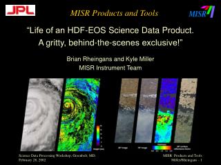
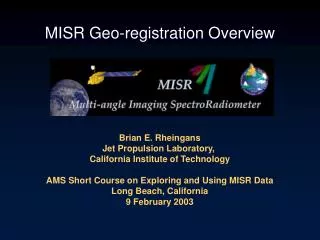
MISR Geo-registration Overview. Brian E. Rheingans Jet Propulsion Laboratory, California Institute of Technology AMS Short Course on Exploring and Using MISR Data Long Beach, California 9 February 2003. MISR Background. Four MISR images over Appalachain Mountains

E N D
MISR Geo-registration Overview Brian E. Rheingans Jet Propulsion Laboratory, California Institute of Technology AMS Short Course on Exploring and Using MISR Data Long Beach, California 9 February 2003
MISR Background Four MISR images over Appalachain Mountains Nadir, 45.6 deg, 60.0 deg, 70.5 deg forward viewing cameras To make use of angular as well as spectral information all (9 cameras X 4 bands = 36) pixels must be accurately co-registered
MISR Background Each MISR camera eventually Views one ground point at a Slightly different time from a Different angle as the spacecraft Passes over that point. Data is resampled from each channel Onto a common map projection, Called Space Oblique Mercator (SOM).
SOM Background The Space Oblique Mercator (SOM) map projection was developed to support LandSat which covers the same large geographic extent as MISR. SOM was designed to minimize the shape distortion and scale errors throughout the length of the MISR swath near the satellite ground track.
SOM Background • Terra follows a pattern of orbits which repeats after 233 unique orbits • Each of the 233 possible orbits is called a path • SOM defines a separate projection for each of these paths • For MISR, a path begins at a particular longitude as the satellite • crosses the ascending node. • This path implies a specific longitude of ascending node, which implies • a specific SOM projection applicable to that path
SOM Background • SOM coordinates are X,Y in meters • X axis points in the approx. direction of the satellite groundtrack • Y axis is perpendicular to the X axis • The origin of X is at the ascending node equator crossing • Once ascending node is reached, X values start over at 0 for the next path/proj. • The sign of Y is relative to the sinusoidal X axis
SOM Background • Line/Sample • Pixels are arranged in a regular 2-D array in SOM space • The indices are absolute line and sample • Given the SOM(X,Y), pixel resolution, and absolute line/sample offset • you can compute the SOM coordinate of any other point in the swath • Blocks • MISR path is cut-up into a series of pre-defined, uniformly-sized SOM • boxes along the ground track, called blocks • For MISR, block-relative lines and samples restart at 0,0 at the top • left of each block and thus MISR has a block number • MISR files are BLOCK-RELATIVE, not absolute.
HDF-EOS Background • Grid • All MISR products are in HDF 4 format • HDF-EOS = HDF 4 + GCTP • HDF-EOS data type for map projected data is called “Grid” • HDF-EOS Grid metadata stores orbital parameters and map • projection parameters • “Stacked Block” Grid • Problem was MISR data (w/ large extent) didn’t fit the Grid model • Extension to the grid model to store MISR blocks • Actually, it is a 3-D array (block, line, sample) • Blocks are stack on top each other with a constant vertical offset (1 block) • The lateral offset is not constant
HDF-EOS Background • Block Offset • Blocks may be shifted left or right by an integral multiple of 17.6 km • Shifts are pre-defined, as is the block locations to encompass MISR footprint • MISR stack-block grid is defined for a given path by the coord. of the first • block, along with standard projection metadata and an array of block offsets • to define the locations of all subsequent blocks.
HDF-EOS Background HDF-EOS routines do NOT assemble the Blocks. That is left for the user. 180 blocks are defined for every MISR Product to make block index in absolute. However, roughly 142 blocks have data for Any given orbit. The extra blocks are to Allow for seasonal variation.
MISR Product Characteristics • MISR L1B2 and above product characteristics: • Space Oblique Mercator (SOM) map projection • Stacked-block HDF-EOS Grid format • Large geographic extent • Determining latitude and longitude of a MISR pixel (2 methods): • 1) Look up in Ancillary Geographic Product (AGP) • One AGP for each Terra orbital path • Separate product • Stored at 1.1km • 2) Convert coordinate systems • Orbital param. and projection info. are in all MISR products • HDF-EOS library access routines used to read metadata • GCTP map projections library used (w/ HDF-EOS) • Algorithm to map between SOM(X,Y) and MISR(b,l.l,s.s) • See Appendix A of the MISR DPS
Coordinate Conversions • Forward Conversion: • Lat/Lon -> SOM(X,Y) -> MISR(b,l.l,s.s) • Useful for resampling MISR data to another projection • Notice line and samples can be fractional • Inverse Conversion: • MISR(b,l.l,s.s) -> SOM(X,Y) -> Lat/Lon • Useful for determining lat/lon of a pixel • Orbit path must be known a priori (metadata is required) • Coordinate conversions are reversible with reasonable numerical • Precision only for positions near the satellite ground track. • Positions not near the ground track are better-described on another • Path and SOM projection.
SOM <-> Lat/Lon • Forward: Lat/Lon -> SOM • Given a pixel’s position in Lat/Lon coordinates assuming a particular • MISR orbit path, SOM(X,Y) in meters can be computed by: • Retrieving projection parameter metadata. • Calling SOM forward routines from the GCTP library. • Inverse: SOM -> Lat/Lon • Given a pixel’s position in SOM(X,Y) meters, assuming a particular • MISR orbit path, Lat/Lon can be computed by: • Retrieving projection parameter metadata • Calling SOM inverse routines from the GCTP library.
Coordinates in other Map Projections • Forward: • AnyProj(X,Y) -> Lat/Lon -> SOM(X,Y) -> MISR(b,l.l,s.s) • Useful for reprojecting to another map projection • Inverse: • MISR(b,l.l,s.s) -> SOM(X,Y) -> Lat/Lon -> AnyProj(X,Y)
Geometric Parameters Product The following Parameters are Stored in the Geometric Product (GMP): View Zenith per camera View Azimuth per camera Solar Zenith Solar Azimuth Scatter Angles per camera Glitter Angles per camera