Download
1 / 7
70 likes | 219 Views
Avalanche Photo-Diodes (APDs) K.Deiters, Q.Ingram, D.Renker, T.Sakhelashvili Paul Scherrer Institute, Villigen, Switzerland J.Grahl, I.Kronqvist, R.Rusack, A.Singovski, P.Vikas University of Minnesota, Minneapolis, USA I.Britvitch, A.Kuznetsov, Y.Musienko, S.Reucroft, J.Swain

E N D
Avalanche Photo-Diodes (APDs) • K.Deiters, Q.Ingram, D.Renker, T.Sakhelashvili • Paul Scherrer Institute, Villigen, Switzerland • J.Grahl, I.Kronqvist, R.Rusack, A.Singovski, P.Vikas • University of Minnesota, Minneapolis, USA • I.Britvitch, A.Kuznetsov, Y.Musienko, S.Reucroft, J.Swain • Northeastern University, Boston, USA • Z.Antunovic, N.Godinovic, I.Soric • University of Split, Croatia • Honorary assistent: J-L.Faure D. Renker PSI
APD History Late 1992: 1st Hamamatsu prototype Early 90th Push for a homogeneous calorimeter 1995: Test of an APD on a PbWO4 crystal in H4 1996-97: APDs chosen for ECAL A comparison of the response to 80 GeV electrons of a lead tungstate crystal with a PIN diode (top) and an APD (bottom) read-out. The tail to the right of the peak in the PIN diode spectrum is due to particles leaking out of the back of the 18 cm long crystal and passing through the diode D. Renker PSI
APD properties D. Renker PSI
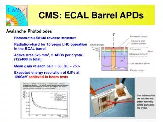
APD properties cont. (1) APDs are insensitive to magnetic fields, are compact, cheap and have a small nuclear counter effect. They are potentially radiation hard. But: they have a small area (5x5 mm2) and they were a widely unknown device D. Renker PSI
Distance of operating to breakdown voltage Stable since 2000 Side remark: Thousands of APDs have been tested and sometimes “accidents” happened. APDs were biased with the wrong polarity for a long period or the bias voltage was far too high (3000 V instead of 300 V). No APD ever died due to such an event. . D. Renker PSI
Reliability tests • Weak or bad APDs are identified by a number of tests after the 60Co irradiation: • is there a change of the breakdown voltage (dVb)? • is the dark current at gain 50 within the limits (Id)? • Is the dark current divided by the gain falling continuously (Id/M vs M)? • Is there an abnormal high noise? • Is the APD coming from a “bad position” on the wafer (mask problem)? • Is the APD coming from a “bad wafer” (problem in the neutron irradiation)? • The same tests are performed after the annealing with the exception of the noise. • The noise is later on measured in Lyon when the APDs have been mounted on • the capsule. • How do we measure these parameters? Yuri • How efficient is the screening? Quentin • What are the rejection criteria? Sasha D. Renker PSI
PROVISIONAL FINAL TECHNICAL SPECIFICATION • General conditions: VR (operating voltage for gain M = 50) and VB (breakdown voltage, at which the dark current exceeds 100 A), as • all other values measured at T = 25 C. For radiation hardness: neutron (1 MeV) fluence 2x10¹³ n/cm2 • Sensitive area 5x5 mm2 • Survival rate after irradiation * 99.9 0.1 % • Survival rate after 2 months at 90º C @ M=50 * 99.9 0.1 % • Survival rate after 1 day at 20 A (V= VB + 20V) (1) *99.9 0.1 % • Passivation layer Si3N4 • Charge collection within 20 ns (2)99 1 % • Capacity at VR (mean value) 65 – 85 pF • Spread of capacity at VR 5 pF • Capacity at VR – Capacity at VB 3 pF • DM/dV·1/M (gain sensitivity to voltage) at VR 3.5 %/V • Quantum efficiency (mean value) (3)75 5 % @ 430 nm • Spread of measured quantum efficiency (3) 7 % • Operating voltage VR 340 – 440 V • Difference VB - VR ** 37 V • Nuclear counter effect leff(4)< 7 m • Excess noise factor at VR2 0.3 @ 430 nm • Dark current Id at VR 50 nA • Serial resistance (mean value) < 5 • Spread of serial resistance 1 • DM/dT·1/M (gain sensitivity to temperature) at VR2 0.5 %/deg Celsius • Ratio of Noise (M=300)/Noise (M=50) (5) 12 • Variation of Id/gain for 50 < M < 400 (6)< 10% rise • Change of QE after irradiation 2 % • Change of gain after irradiation (7) 3 % • Dark current (bulk) after irradiation (7) 5 A • Spread of Id (total) at VR after irradiation (7) 0.5 A • Difference VB-VR after irradiation (7)> 30 V D. Renker PSI