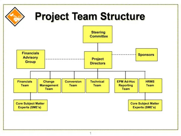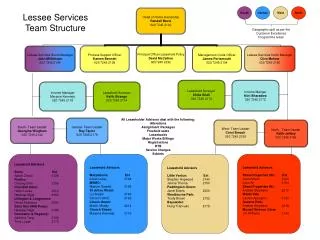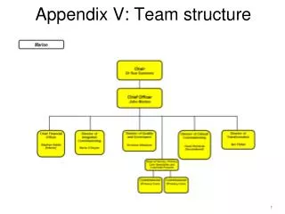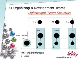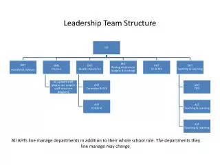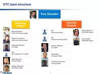
Team Structure
Team Structure. Project Schedule. High Voltage System. High Voltage System split into two major subsystems: Tractive System : 75 kW nominal power output 84 kW peak power output Safety and Shutdown System:


Team Structure
E N D
Presentation Transcript
High Voltage System • High Voltage System split into two major subsystems: • Tractive System: • 75 kW nominal power output • 84 kW peak power output • Safety and Shutdown System: • Monitors vehicle for possible faults from Ground Fault, Battery Management and others • If a problem is detected will disengage the Tractive System until operator action is taken • Completely removes positive and negative terminals from Tractive System in less than 15mS • Drops voltage of Tractive System to under 40V in less than 1s
High Voltage System – Test Procedure • Assemble battery packs • Test Shutdown circuit • Connect contactors and test clearing faults, buttons properly control contactors. • Test Discharge circuit • Connect circuit to contactors. • When DC- is off resistance between DC+ and DC- should be 2k. • When DC+ is on resistance should be open. • Connect Motor controller LV systems • Test basic motor controller operation • Connect DC- to motor controller. • Connect 3Phase lines to motor. • Connect resolver interface. • Connect to CAN bus. • CAN I/O determines operation.
High Voltage System – Test Procedure (cont) • Test Pre-charge circuit • Connect to battery side of DC+ • Connect relay to controller interface. • Connect pre-charge output to motor controller DC+ • Test Operation • If Pre-charge High turns off and DC+ turns on operation is OK • Calibrate motor controller resolver interface. • Follow RMS manual. • Connect DC+ to motor controller. • Power Unit on. • Test CAN control • If motor moves test is success.
High Voltage System – Risk Mitigation • Shock hazard • Rubber lined leather gloves used to handle HV energized components • Indicators when system is energized external of battery boxes • Runaway car hazard • Multiple ‘on’ indicators as well as multiple emergency shutdown systems
Other Risk mitigation available: • Failure Mode Effects Analysis (106 various failures and corrective actions taken by team)
Other Risk mitigation available: • Electrical Safety Form • 90 Pages, 10,948 Words (Revision 5) • Details every electrical component and system used in the car.
Accumulation System • Total 6.8 kWh capacity. • Total of 288 cells • Nominal voltage of 266.4, with a max of 302.4 VDC.
LiPo Cells - Risk Mitigation • If exposed to a fire, added mechanical shocks, decomposed, added electric stress by miss-use. The cell case will be breached at the extreme, and hazardous materials may be released. • Extinguishing Media: Water, carbon dioxide gas, chemical power fire extinguishing medium and fire foam. • Conditions to avoid: When a cell is exposed to an external short-circuit, crushes, deformation, high temperature above 100 degree C, direct sunlight and high humidity. • We plan to do testing, on spare cells at just above our operating specifications (a.k.a destructive testing)
Battery Packs - Update • Being assembled now, using custom Kevlar boxes. • The tabs of each cell are extremely strong, and made out of aluminum. Each tab which will have a ¼ inch hole that will allow copper busbars to be attached • Copper busbars (sized to handle in excess of 400A) • Kevlar Insulating Cover (Surface Resistivity of 10^12-10^14 Ohms • Series connections between packs will be made by Anderson connectors (350 A).
Accumulator Testing with BMS • As mentioned, each cell is numbered. This will allow us to pull data from the BMS and know exactly which cell is at what voltage and temp. • Connect all battery packs together and verify total voltage. We will then charge the accumulator to its maximum voltage of 302 VDC. • Once they are charged, discharge bench testing using Motor Controller and Motors. • The BMS will keep track of all voltages and temperatures over time. Repeat this process until we have enough data to accurately model the batteries as a whole unit. Develop discharge and charging curves for normal operations. • Using this data, improve the system for next year.
Battery Packs - Risk Mitigation • Packs will be built cell by cell, one person may only build one pack at a time. All cells are numbered for inventory, tracking, and testing purposes. • Once a pack is complete, individual cells will be tested for correct voltage, and good electrical/mechanical contacts. Entire pack voltage will be confirmed. • Repeat the process nine times.
Control System • Control of the car is a closed loop system in which throttle input from the drive is modified by various environmental factors to optimize desired outcome • So far: • All Low voltage parts, connectors and wiring resources have been selected and received. • Plans have been made with Mechanical Engineers to incorporate sensors into the car. • Wiring harness and low voltage boxes have been designed and construction is underway. • Next: • Finish construction of harness and boxes. • Preform out of car testing. • Mount systems in car and preform final continuity tests.
Control System – Test Procedure • Each individual wired connection will be multimeter tested to ensure viability. • Mechanical strength of crimped connections will be tested. • Current draw on each fuse will be measured with a multimeter so that fused lines can be combined appropriately. • Time allowing, current draw of all lines will be tested to determine whether a smaller gauge of wiring would be possible. • Control system software will be verified using potentiometers as stand-ins for sensors.
Control System – Risk Mitigation • Modular system allows individual sections of harness or LV boxes to be removed, tested and replaced if necessary. • Fallback system with single arduino connected directly to throttle and brakes will kick in if the sensor grid or control software fails. • Incorporating resistors into sensor power lines should prevent single sensor failure from shorting other sensors on the same fuse. • Debug panel with status indicators and interfaces for all controllers should allow quick identification of problems. • Safety features such as tractive system active light and ready to drive sound to help prevent accidents when working on the car.
Regenerative braking - System test • To test out the effectiveness of regenerative braking, the motor will be increased to a certain RPM with no load on a bench and full braking will be then applied. • Battery current and voltage, time and acceleration will be recorded. • From this data, we should be able to calculate: • Kinetic energy lost during the electric braking test from 65 mph to 0mph. • Electric energy gained during electric braking test from 65 mph to 0 mph. • Efficiency of converting kinetic to electric energy. • Braking torque during the mechanical and electric test.
Regenerative Braking - Risk Assessment • Power generated from regenerative braking exceeds the charging capacity of the batteries. • The motor controllers have the ability to limit the current. • A supercapacitorcan be used to store the energy temporarily and allow more of the energy to go to the batteries. • Since regenerative braking will only be applied to the rear wheels, some instability may occur. • This may be mitigated by testing the stopping power of the regenerative braking system on a dynamometer before attempting a test on the track.