Download
1 / 10
110 likes | 238 Views
THE ISLANDING PROBLEM. After system switching operation, a section of the utility network remains connected to the DG !. HV Busbar. MV Busbar.

E N D
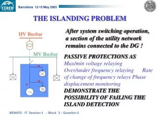
THE ISLANDING PROBLEM After system switching operation, a section of the utility network remains connected to the DG ! HV Busbar MV Busbar PASSIVE PROTECTIONS AS Max/min voltage relaying Over/under frequency relaying Rate of change of frequency relays Phase displacement monitoring DEMONSTRATE THE POSSIBILITY OF FAILING THE ISLAND DETECTION
DLC-BASED PROTECTION SCHEME Guard frequency injected at MV busbar Under normal conditions, guard frequency detected by RX
When the breaker is opened there is a loss of guard frequency for the DG receiver
FEASIBILITY OF DLC PROTECTION THE CARRIER SIGNAL PROPAGATION IN MV NETWORKS CAN FIND DIFFICULTIES DUE TO: Ø overhead and cable line attenuation; Ø the presence of capacitor banks; Ø different line segments; Ø branching; Ø mismatching and standing wave patterns.
DEVELOPMENT OF A TOOL FOR THE CARRIER SIGNAL TRANSMISSION ANALYSIS OPTIMAL MISMATCHING ZONE STANDING WAVE CONDITIONS Cable Lines ZM = 460 Overhead Lines ZM = 3000 Combination of OHL and CL ZM = 1500
0.70 1.25 Conductors ACSR =15.85 mm CC =10.70 mm 10.25 m MV overerhead line Attenuation as a function of receiver impedance ZM less than 0.5 [dB/km] about 1.54 [dB/km] OVERHEAD AND CABLE LINE ATTENUATION
Electric circuit The Coupling Capacitance : EXAMPLE OF A CAPACITIVE COUPLING DEVICE
Comparison between computed and measured values MEASUREMENT CAMPAIGN I URBAN FEEDER ATTENUATION at 72 kHz = 20 db GOOD AGREEMENT !
TX: 20 db on 75 RX: -49.37 db ATTENUATION: 70 db MEASUREMENT CAMPAIGN II RURAL RADIAL FEEDER This measurement campaign seems to be representative of the DLC transmission length limit without the use of repeater devices.
CONCLUSION • A novel protection method to prevent DG islanding; • A suitable analysis procedure has been developed; • Good agreement of test results with the theoretical calculations (accuracy of the multiconductor matrix procedure); • Distance limit between TX and RX about 10 15 km for a typical Italian radial branched MV feeder; • (If longer distances are needed, the use of repeaters must be taken into consideration).