Download
1 / 36
360 likes | 525 Views
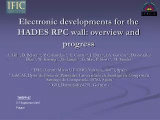
Electronic developments for the HADES RPC wall: overview and progress. A. Gil a , D. Belver b , P. Cabanelas b , E. Castro b , J. Díaz a , J.A. Garzón b , D.González-Díaz c , W. Koenig c , J.S. Lange c , G. May, P. Skott c , M. Traxler c

E N D
Electronic developments for the HADES RPC wall: overview and progress A. Gil a, D. Belver b, P. Cabanelas b, E. Castro b, J. Díaz a, J.A. Garzón b, D.González-Díaz c, W. Koenig c, J.S. Lange c, G. May, P. Skott c, M. Traxler c a IFIC (Centro Mixto UV-CSIC) Valencia, 46071, Spain. b LabCAF, Dpto. de Física de Partículas, Universidade de Santiago de Compostela, Santiago de Compostela, 15782, Spain. c GSI, Darmstadt,64291, Germany. TWEPP-07 3-7 September 2007 Prague
OUTLINE • INTRODUCTION TO HADES EXPERIMENT • OVERVIEW OF TESTED ELECTRONICS • FRONT-END ELECTRONICS • DAUGHTERBOARD • MOTHERBOARD • READ OUT SYSTEM • RESULTS • CURRENT PROGRESS: NEW DEVELOPED ELECTRONICS • PLAN FOR THE NEXT TESTS
OUTLINE • INTRODUCTION TO HADES EXPERIMENT • OVERVIEW OF TESTED ELECTRONICS • FRONT-END ELECTRONICS • DAUGHTERBOARD • MOTHERBOARD • READ OUT SYSTEM • RESULTS • CURRENT PROGRESS: NEW DEVELOPED ELECTRONICS • PLAN FOR THE NEXT TESTS
HADES EXPERIMENT High Acceptance DiElectonSpectrometer Located at the SIS accelerator of GSI, Darmstadt (Germany) • Detection of electron-positron pairs produced in relativistic hadron-nucleus and nucleus-nucleus collisions with the goal of studying vector meson properties in nuclear matter, both normal and hot and compressed. • Consists of several subdetectors for: • Tracking • Triggering • Particle identification • Momentum reconstruction Goal of the Hades RPC project: upgrade the low angles Time of Flight (TOF) detector
HADES EXPERIMENT • Area of polar angles <45º • low particle rate(up to 700 Hz/cm2) Existing temporary low angles TOF detector (called TOFino): - Low time resolution (350ps) • - Low granularity RPC Beam RICH Target • Upgrade using RPC technology: • Time resolutions lower than 100ps • Cost-effective solution MDCs Coil TOFino TOF MDCs Shower Cross section of HADES Front view from inside
Double layer Acceptance close to 100% RPC wall Sectors are filled with RPC cells The RPC wall contains 1024 double-sided readout cells (2048 channels) • 80 times larger granularity Will allow collisions from C-C to Au-Au at 1.5GeV
RPC cells RPC Gas Box & cells(P. Fonte et al. LIP-Coimbra) • CHEAP MATERIALS: • Aluminium • Glass • SHIELDED CELLS: • Crosstalk < 1% • STANDARD GAS MIXTURE: • Freon (85%) • SF6 (15%) • Isobutane (5%) Structure of the HADES RPC cells
OUTLINE • INTRODUCTION TO HADES EXPERIMENT • OVERVIEW OF TESTED ELECTRONICS • FRONT-END ELECTRONICS • DAUGHTERBOARD • MOTHERBOARD • READ OUT SYSTEM • RESULTS • CURRENT PROGRESS: NEW DEVELOPED ELECTRONICS • PLAN FOR THE NEXT TESTS
MB DB RPC cells TRB To ethernet ELECTRONICS Front End Read out system
MB DB RPC cells TRB To ethernet ELECTRONICS Front End
Detector active area FRONT END ELECTRONICS Not enough number of channels to design an ASIC Built with commercially available components Space restrictions due to geometry Requires low power consumption to avoid heating problems • INPUT: Short analog pulses (about 500ps rise time and 5ns width) from the RPC cells. 50mV 100ns Electronic requirements: • A large bandwidth to deal with the short rise times • Low electronic jitter and noise for good time resolutions Front End set up on the RPC sector
DAUGHTERBOARD • Takes analog signals from 2 RPC cells and provides a digital output pulses • 4 electronic channels/board (two in each side) • All SMT components (0603 size of R & C) • 6 Layer board 4 2 4.5cm 1 2 3 4 5cm Back side Front side
Small walk error due to: -Small rise time Further reduction by: -Decreasing TOF thr. -Charge correction Walk error Latch enable C MAX9601-2ch Q OPA690 Wideband Op. Amplifier Q/ C Integrator ToT-Threshold DAUGHTERBOARD • Generates a timing-signal (output pulse) . It contains information about: • Arrival time (for TOF measurement)Leading edge • ChargeWidth(Trailing edge) Ideal correction width~charge Arrival time PECL comparator R Trigger Out. Σ4ch. Amplifier MAX9601-2ch (500ps Propagation Delay) 2k2 In Q BFT92 Wideband PNP Transistor Q/ C Latch enable ToF-Threshold 4 ch. out GALI-S66 Monolithic (20dB, 2GHz) PECL- LVDS SN65LVDT100 SAMTEC 16 diff. pins
DAUGHTERBOARD ToF xG RPC signal ƒ ToT Voltage (50mV/div) Integrated signal TOT thr RPC arrival time TOF thr Amplified RPC signal Output pulse width~charge Time (100ns/div)
+5V -5V +3.3V DC input DAC DAC DAC DAC DAC DAC DAC DAC inverters inverters inverters inverters inverters inverters inverters inverters Connector to DB Connector to DB Connector to DB Connector to DB Connector to DB Connector to DB Connector to DB Connector to DB DC filter DC filter DC filter DC filter MOTHERBOARD • Part of the Front End Electronics that did not fit on the Daughterboard interfaces DB with Readout system • Provides support to 32 channels (8 DB) • 12 layer board Connector to TRB LVDS conv Low level trigger (N to 1) Test signal distribution
MOTHERBOARD • 32 channels • 12 Layer board • Main tasks: • Delivers the timing-signals from 8 Daughterboard to the Read out board. • Supply stable voltage to the Daughterboards (+5V,-5V,+3.3V) • Combines the 32 multiplicity signals coming out from the Daughterboard to provide a low level trigger signal. • Allocates DACs for the threshold voltages of the comparators on the Daugherboard • Minor tasks: Test signals distribution, LVDS repeaters,interface for DAC programming, etc 6cm 40cm
MOTHERBOARD Interface: Low Voltage Differential Signaling (LVDS) Advantages: • Low power consumption • High noise inmunity Diferential impedance matching lines and termination resistors (100Ω) to reduce signal reflections/distorsions
MOTHERBOARD • Main tasks: • Delivers the timing-signals from 8 Daughterboard to the Read out board. • Supply stable voltages to the Daughterboards (+5V,-5V,+3.3V) • Combines the 32 multiplicity signals coming out from the Daughterboard to provide a low level trigger signal. • Allocates DACs for the threshold voltages of the comparators on the Daugherboard • Minor tasks: Test signals distribution, LVDS repeaters,interface for DAC programming, etc 6cm 40cm
MOTHERBOARD Ripple filtering: Low Dropout Regulators DC-DC converter Motherboard +5V -5V ch1 +3.3V ch2 Noise filtering: Ferrite beads + low ESL capacitors • +5V,+3.3V: ADP3338 (1A) • -5V: LT1175 (0.5A) 1 regulator block every two channels ( from DC up to 10-200Kilohertz) MIN VOLTAGE DROP:~350mV MIN VOLTAGE DROP:~200mV
MOTHERBOARD • Main tasks: • Delivers the timing-signals from 8 Daughterboard to the Read out board. • Supply stable voltages to the Daughterboards (+5V,-5V,+3.3V) • Combines the 32 multiplicity signals coming out from the Daughterboard to provide a low level trigger signal. • Allocates DACs for the threshold voltages of the comparators on the Daugherboard • Minor tasks: Test signals distribution, LVDS repeaters,interface for DAC programming, etc 6cm 40cm
MOTHERBOARD Low level trigger output: • Two-stage circuit • Summing OPAMs • OPA690 • High slew rate • High output swing • -100mV contribution per channel Rate < 1kHz/cm2 RPC area x100cm2 =100kHz X31 channels = 3.1 MHz firing
MOTHERBOARD • Main tasks: • Delivers the timing-signals from 8 Daughterboard to the Read out board. • Supply stable voltages to the Daughterboards (+5V,-5V,+3.3V) • Combines the 32 multiplicity signals coming out from the Daughterboard to provide a low level trigger signal. • Allocates DACs for the threshold voltages of the comparators on the Daugherboard • Minor tasks: Test signals distribution, LVDS repeaters,interface for DAC programming, etc 6cm 40cm
DAC1 DAC2 DAC8 MOTHERBOARD DAC thresholds • Programable by SPI • 8 DAC chips/Motherboard • 8 Channels/DAC chip • Daisy-chained • LTC2620 (12 bits resolution) • Feedback for data transmission error detection Read out board DIN DOCSCLK Motherboard TTL to LVDS converter LVDS to TTL converters
MOTHERBOARD • Main tasks: • Delivers the timing-signals from 8 Daughterboard to the Read out board. • Supply stable voltages to the Daughterboards (+5V,-5V,+3.3V) • Combines the 32 multiplicity signals coming out from the Daughterboard to provide a low level trigger signal. • Allocates DACs for the threshold voltages of the comparators on the Daugherboard • Minor tasks: Test signals distribution, LVDS repeaters,interface for DAC programming, etc 6cm 40cm
MB DB RPC cells TRB To ethernet ELECTRONICS Read out system
HPTDC HPTDC HPTDC HPTDC READ OUT SYSTEM • 4x32 channels HPTDC • 80 pin twisted parir cable, KEL connector • Single chip computer with ethernet (ETRAX) • FPGA • DC/DC 48V, isolated • Memory TRB (TDC Readout Board): • Custom board • Based on the HPTDC ASIC developed at CERN • 128-channel Front End Board Controller FPGA Trigger bus Optional DSP processing LVL1 queue LVL2 queue CPU Ethernet GSI (M. Traxler et al.)
RESULTS Full chain:Detector+FEE+TRB • Tests with gamma illumination using 60Co source: • <0.5W/channel • Crosstalk<1% Output width vs charge correlation for gamma illumination using 60Co source ToFThr=15mV ToTThr=-20mV Time of Flight measurements
RESULTS • Test with RPC signals under C-C (1.5 GeV) collisions 80 ps Sector prototype with 48 channels 77 ps Crosstalk 2%-6%
OUTLINE • INTRODUCTION TO HADES EXPERIMENT • OVERVIEW OF TESTED ELECTRONICS • FRONT-END ELECTRONICS • DAUGHTERBOARD • MOTHERBOARD • READ OUT SYSTEM • RESULTS • CURRENT PROGRESS: NEW DEVELOPED ELECTRONICS • PLAN FOR THE NEXT TESTS
DAUGHTERBOARD • Improved charge measurement • Used a more gain preamplifier • 2nd integration for linearity • Only one comparator 30% power consumption reduction R Discriminator Step Σ4ch. Trigger Out. Amplifier Step MAX9601-2ch 500ps Propagation Delay 2k2 In Q Q/ BFT92 Wideband PNP Transistor C C Latch enable/ 4 ch. out BGM1013 Monolithic (31dB, 2.2GHz) PECL- LVDS ToF-Threshold C 2nd integration RC=20ns SN65LVDT100 OPA690 Wideband Op. Amplifier R SAMTEC 16 diff. pins ToT Integrator Charge comparator removed
Saturation Linear DAUGHTERBOARD Benefits: • linearity of the charge measurement (by adjusting integration values) • More dynamic range
MOTHERBOARD • 2 only modifications: • Addition of common mode filters at the power input • Cooper area at the bottom ground improvement 6cm 40cm
HPTDC HPTDC HPTDC HPTDC READ OUT SYSTEM New general purpose Readout: • Layout bugs corrected • New FPGA (VIRTEX4) • New DSP (TigerSharc) • Detector independent: Also for PANDA & CBM • Add-on board concept: 32 LVDS input lines Front End Board Controller FPGA 32input LVDS lines Optical link (2Gbit/s) Optional DSP processing LVL1 queue LVL2 queue CPU Ethernet
OUTLINE • INTRODUCTION TO HADES EXPERIMENT • OVERVIEW OF TESTED ELECTRONICS • FRONT-END ELECTRONICS • DAUGHTERBOARD • MOTHERBOARD • READ OUT SYSTEM • RESULTS • CURRENT PROGRESS: NEW DEVELOPED ELECTRONICS • PLAN FOR THE NEXT TESTS
PLAN FOR NEXT TESTS • FULL SECTOR TEST • 350 channels • Sector gas box ready. • New electronics already developed. Produced: • 12 MB & 4 miniMB • 108 DB • 4 TRB (Read out) • Currently being assembled Gas box wiew without front cover