Download
1 / 22
410 likes | 1.22k Views
Revisit CMOS Power Dissipation. Digital inverter: Active (dynamic) power Leakage power Short-circuit power (ignored). Roy & Prasad (2000). Leakage vs. Active Power Trends. W. Haensch , IBM J. Res. Dev. 50, 339 (2006). Some Observations with Leakage.

E N D
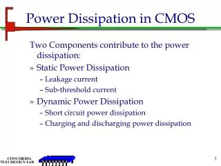
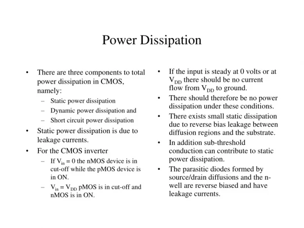
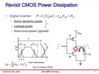
Revisit CMOS Power Dissipation • Digital inverter: • Active (dynamic) power • Leakage power • Short-circuit power (ignored) Roy & Prasad (2000)
Leakage vs. Active Power Trends W. Haensch, IBM J. Res. Dev. 50, 339 (2006)
Some Observations with Leakage • This is the “usual” (BSIM, Spice) leakage model • The thermal voltage VT = kBT/q • This model was derived for 3-dimensional carrier motion, impinging on a small energy barrier (what about 1-D or 2-D transistors?) • This model assumes some average “junction temperature” T but T itself is unsteady during digital operation! (what about hot phonons?!)
What About Energy? • Energy is a better metric when worried about battery life • So look at energy, not power minimization: • Critical difference: leakage energy depends on circuit delay, tp ?
Effects of Lowering VDD B. Zhai, IEEE Trans. VLSI Sys. 13, 1239 (2005) • Easy observation: lowering VDD lowers power and energy… the latter up to a point! • How low VDD? • It is theoretically possible to operate circuits near VDD ~ 50 mV, deep into the subthreshold regime! • So… why not do it?
Energy-Voltage Trade-Off B. Zhai, IEEE Trans. VLSI Sys. 13, 1239 (2005) • Remember, delay: • At high VDD ION = ID,sat • At low VDD delay too high, so leakage energy goes up as well Optimum VDD!
Principles of Low-Power Design Roy & Prasad (2000) • Use the lowest possible supply voltage (VDD) • Use the smallest geometry, highest frequency devices BUT operate them at the lowest possible frequency (f) • Use parallelism and pipelining to lower required frequency of operation • Manage power by disconnecting power source when system is idle (sleep states) • Design systems to have lowest requirements of performance for the given user functionality
Leakage Model: Closer Look • Strongly (exponentially!) temperature dependent! • Typically people use ΔT = PRTH where • ΔT is an average “junction temperature” • P is a time-averaged power dissipation (active + leakage) • How do we calculate RTH? • And when is it OK to use it?
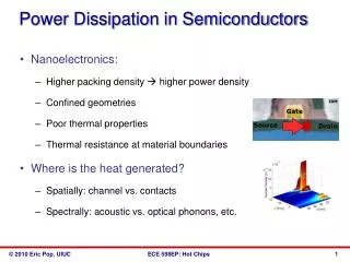
Device Thermal Resistance Data • High thermal resistances: • SWNT due to small thermal conductance (very small d ~ 2 nm) • Others due to low thermal conductivity, decreasing dimensions, increased role of interfaces Single-wall nanotube Phase-change Memory (PCM) Silicon-on- Insulator FET Cu Via • Power input also matters: • SWNT ~ 0.01-0.1 mW • Others ~ 0.1-1 mW Bulk FET Data: Mautry (1990), Bunyan (1992), Su (1994), Lee (1995), Jenkins (1995), Tenbroek (1996), Jin (2001), Reyboz (2004), Javey (2004), Seidel (2004), Pop (2004-6), Maune (2006).
Modeling Device Thermal Response • Steady-state models • Lumped: Mautry (1990), Goodson-Su (1994-5), Pop (2004), Darwish (2005) • Finite-Element SOI FET Bulk FET D tSi W L tBOX Bulk Si FET SOI FET
Modeling Device Thermal Response • Transient Models • Lumped: Tenbroek (1997), Rinaldi (2001), Lin (2004) • Introduce CTH usually with approximate Green’s functions; heated volume is a function of time (Joy, 1970) • Finite-Element Instantaneous T rise Due to very sharp heating pulse t ‹‹ V2/3/ More general Simplest (~ bulk Si FET) Temperature evolution anywhere (r,t) due to arbitrary heating function P(0<t’<t) inside volume V (dV’ V) (Joy 1970) Temperature evolution of a step-heated point source into silicon half-plane (Mautry 1990)
Approaches for Thermal Resistance • Time scale: • Transient • Steady-State • Geometric complexity: • Lumped element (shape factors) • Analytic • Finite element (Fourier law) + Interconnect
Shape Factors Sunderland, ASHRAE (1964), many others • Heat flux: q = Sk(T1-T0) • Equivalent thermal resistance RTH = 1/Sk
Ex: Heat Loss from Via + Interconnect Chen, Li, Rosenbaum, Kang, IEEE TCAD ICS 19, 197 (2000) Cu Estimating heat loss (thermal resistance) “looking into” one Cu line: Typical values SiO2 zTOP 2r w d Chen, 2000 zBOT K/mW (bot – top) Si
Obtaining the Temperature Distribution • Now we want temperature distribution T(x) in 1-D • Consider power in/out of a 1-D element • Simplest case: Si layer on SiO2/Si substrate (SOI) • Or interconnect on thermally insulating SiO2
1-D Interconnect with Heat Generation L x+dx x Heat: d W Electrical: tox SiO2 Energy balance equation for 1-D element “dx”: pick units of J/cm3 or W/cm3 (W = J/s) T0 Si Energy In (here, Joule heat) = Energy Out (left, right, bottom) + Change in Internal Energy
1-Dimensional Heat Equation unsteady (transient) DT k SiO2 DT g steady, with convection SiO2
Carbon Nanotube (Cylinder) DT Role of cylindrical heat spreading (shape factor!) Role of thermal contact resistance E. Pop et al. J. Appl. Phys. 101, 093710 (2007)