Download
1 / 35
350 likes | 526 Views
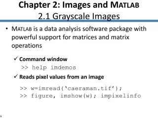
Introduction to M ATLAB. Basic Graphics. www.opencadd.com.br. Section Outline. 2-D plotting Graph Annotation Subplots & Alternative Axes 3-D plotting Specialized plotting routines Patches & Images Saving & Exporting Figures Introduction to Handle Graphics.

E N D
Introduction to MATLAB Basic Graphics www.opencadd.com.br
Section Outline • 2-D plotting • Graph Annotation • Subplots & Alternative Axes • 3-D plotting • Specialized plotting routines • Patches & Images • Saving & Exporting Figures • Introduction to Handle Graphics Ref: Color, Linestyle, Marker options Special characters using LaTeX
2-D Plotting • Specify x-data and/or y-data • Specify color, line style and marker symbol (Default values used if ‘clmnot specified) • Syntax: • Plotting single line: • Plotting multiple lines: plot(xdata, ydata, 'color_linestyle_marker') plot(x1, y1, 'clm1', x2, y2, 'clm2', ...) Ref: Color, Linestyle, Marker options
2-D Plotting - example Create a Blue Sine Wave » x = 0:.1:2*pi; » y = sin(x); » plot(x,y) • plot_2d
Adding a Grid • GRID ON creates a grid on the current figure • GRID OFF turns off the grid from the current figure • GRID toggles the grid state • grid on
Adding additional plots to a figure • HOLD ON holds the current plot • HOLD OFF releases hold on current plot • HOLD toggles the hold state • » x = 0:.1:2*pi; • y = sin(x); • » plot(x,y,'b') • » grid on • » hold on • » plot(x,exp(-x),'r:*') »addgraph
Controlling viewing area • ZOOM ON allows user to select viewing area • ZOOM OFF prevents zooming operations • ZOOM toggles the zoom state • AXIS sets axis range • [xmin xmax ymin ymax] » axis([0 2*pi 0 1])
Graph Annotation LEGEND TITLE TEXT or GTEXT YLABEL XLABEL »annotation
Plot Editor • Enable Plotting Editing • Add Text • Add Arrow • Add Line • Zoom In • Zoom Out • Rotate 3D • [Edit] -> Copy Figure / Options Right click (Ctrl-LFT): on graphics objects to modify properties »plotedit
Using LaTeX in Graph Annotations Font Type (applies inside {} or until changed): • \fontname{ } AND \fontsize{ } Appearance (applies inside {} or until removed): • \bf boldface • \it OR \sl italics OR slanted • \rm remove text formatting (normal) Subscript “_” or superscript “^”: Applies to next character or {text in curly braces} Greek letters and Symbols (prefix with “\”): Selected symbols, e.g. '\pi' = »latex_examp Ref: Special characters using LaTeX
Exercise: 2-D Plotting Create the following graph: fontsize (14) sin(10t) cos(10t) Courier New + Bold
Solution: 2-D Plotting • t = 0:0.01:0.5; • plot(t,sin(10*pi*t),'g-*', ... • t,cos(10*pi*t),'k:o') • title(['\fontsize{14}In-Phase ({\itsolid})', ... • 'and Quadrature ({\itdotted}) Signals']) • xlabel('\fontname{Courier New}\bfTime (\mus)') • ylabel('{\it''Normalized''} Signals'); • text(0.2, cos(2*pi)+0.1, '\leftarrow----\rightarrow'); • text(0.175, cos(2*pi)+0.2, '^\pi/_2 phase lag'); • axis([0 0.5 -1.5 1.5]); • % NOTE: Could have also used GTEXT or PLOTEDIT: • % ============================================= • % gtext('\leftarrow----\rightarrow'); • % gtext('^\pi/_2 phase lag'); »plot2d_soln
Subplots SUBPLOT- display multiple axes in the same figure window subplot(#rows, #cols, index) • subplot(2,2,1); • plot(1:10) • subplot(2,2,2) • x = 0:.1:2*pi; • plot(x,sin(x)) • subplot(2,2,3) • x = 0:.1:2*pi; • plot(x,exp(-x),’r’) • subplot(2,2,4) • plot(peaks) »subplotex
Alternative Scales for Axes LOGLOG Both axes logarithmic SEMILOGY log Y linear X SEMILOGX log X linear Y PLOTYY 2 sets of linear axes »other_axes
3-D Line Plotting plot3(xdata, ydata, zdata, 'clm', ...) » z = 0:0.1:40; » x = cos(z); » y = sin(z); » plot3(x,y,z) »plot_3d Ref: Color, Linestyle, Marker options
3-D Surface Plotting »surf_3d
x Exercise: 3-D Plotting • Data from a water jet experiment suggests the following non-linear model for the 2-D stress in the cantilever beam’s horizontal plane. where: = localized planar stress [MPa] x = distance from end of beam [10-1m] y = distance from centerline of beam [10-1m] • For the particular setup used: (x = {0 to 6}, y = {-3 to 3}, = = = 1, = -0.2) • Plot the resulting stress distribution = e-x[sin(x)*cos(y)]
Solution: 3-D Plotting • B = -0.2; • x = 0:0.1:2*pi; • y = -pi/2:0.1:pi/2; • [x,y] = meshgrid(x,y); • z = exp(B*x).*sin(x).*cos(y); • surf(x,y,z) »plot3d_soln
Specialized Plotting Routines »spec_plots
Specialized Plotting Routines (2) »spec_plots2
Use Row 2 of colormap for pixel (1,2) Row 2 Images Reduced Memory Requirements: Images represented as UINT8 - 1 byte » a = magic(4) a = 16 2 3 13 5 11 10 8 9 7 6 12 4 14 15 1 » image(a); » map = hsv(16) map = 1.0000 0 0 1.0000 0.3750 0 1.0000 0.7500 0 ..... » colormap(map) »imagex
Example: Images » load cape » image(X) » colormap(map)
Saving Figures • 2 files created: • .m - text file • .mat - binary data file. »plot3d_soln
Printing Figures • using the Dialog Box: File Menu / Print... >>printdlg • from Command Line: (Switches are optional) • Controlling Page Layout: File Menu / Page Position >>pagedlg print -devicetype -options
Exporting Figures • Printing image to a file: • Print Dialog Box: (File / Print...) >>printdlg • Command Line: (Switches are optional) • Copying to Clipboard: • Options: (File / Preferences) • Copying: (Edit / Copy Figure) print -devicetype -options filename
Introduction to Handle Graphics • Graphics in MATLAB consist of objects • Every graphics objects has a unique handle and a set of properties which define it’s appearance. • Objects are arranged in terms of a set hierarchy
Root object Figure object Figure object Figure object UIMenu objects UIMenu objects UIControl objects UIControl objects Axes object Axes object Surface object Line objects Text objects Hierarchy of Graphics Objects
Obtaining an Object’s Handle 1. Upon Creation 2. Utility Functions • 0 - root object handle • gcf - current figure handle • gca - current axis handle • gco - current object handle 3. FINDOBJ h_line = plot(x_data, y_data, ...) • What is the current object? • Last object created • OR • Last object clicked h_obj = findobj(h_parent, 'Property', 'Value', ...) Default = 0 (root object)
Deleting Objects - DELETE delete(h_object) » addgraph » h = findobj('Color', [0 0 1]) » delete(h)
Modifying Object PropertiesUsing GET & SET • Obtaining a list of current properties: • Obtaining a list of settable properties: • Modifying an object’s properties: get(h_object) set(h_object) set(h_object, 'PropertyName', 'New_Value', ...) Ref: HELPDESK - Handle Graphics Objects: \help\techdoc\infotool\hgprop\doc_frame.html
Modifying Object PropertiesUsing the Property Editor Object Browser: Hierarchical list of graphics objects Property / Value Fields: Selected property & current value (modify here) Property List: List of properties & current values for selected object »propedit
Working with Defaults - setting • Most properties have pre-defined 'factory' values (Used whenever property values are not specified.) • You can define your own 'default' values to be used for creating new objects. (Put default settings in “startup.m” to apply to whole session) Syntax: set(ancestor,'Default<Object><Property>',<Property_Val>) Use root object (0) to apply to all new objects
Set the EdgeColor to Green » set(h, 'EdgeColor', 'g') Reset back to Default Value » set(h, 'EdgeColor', 'default') specifies Default value Reset back to Factory Value » set(h, 'EdgeColor', 'factory') specifies Factory value Example: Working with Defaults Set the Default Surface EdgeColor to Blue & create new surface. • » set(0, 'DefaultSurfaceEdgeColor', 'b') • » h=surf(peaks(15)); • defaults
Working with Defaults - removing Return Default Property Value to Factory Setting: Create a new surface: • » set(gcf, 'DefaultSurfaceEdgeColor', 'factory') OR • » set(gcf, 'DefaultSurfaceEdgeColor', 'remove') • » h = surf(peaks(15)); • defaults