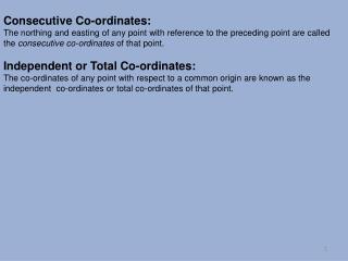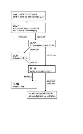
ALTERNATIVE CO-ORDINATES SYSTEM FOR AFS DRAFT REGULATION
150 likes | 333 Views
Informal document No. 11 (50 th GRE, 7-11 April 2003, agenda item 3.3.). ALTERNATIVE CO-ORDINATES SYSTEM FOR AFS DRAFT REGULATION. EXPLANATION TO INFORMAL DOCUMENT No. 10. Tomasz Targosiński Poland. This document is distributed to the Experts on Lighting and Light-Signalling only.

ALTERNATIVE CO-ORDINATES SYSTEM FOR AFS DRAFT REGULATION
E N D
Presentation Transcript
Informal document No. 11 (50th GRE, 7-11 April 2003, agenda item 3.3.) ALTERNATIVE CO-ORDINATES SYSTEM FOR AFS DRAFT REGULATION EXPLANATION TO INFORMAL DOCUMENT No. 10 Tomasz Targosiński Poland This document is distributed to the Experts on Lighting and Light-Signalling only. The document as a whole or in parts cannot be used for other purposes than GRE without written permission of the author.
MEASURING POINTS AND SEGMENTS ON 25 M SCREEN PROPOSED IN DRAFT XXX
AFS LIGHTING UNITS PLACEMENT(DRAFT AMENDMENTS TO R48) AFS lighting units location is more complex than standard headlamps. Standard headlamps are placed symmetrically in fixed height. For AFS the number of units, vertical distance and different heights of mounting are important as described in draft amendments to R48. In this situation only proper units adjustment gives acceptable road illumination.
THE 25 M MEASURING SCREEN INTERSECTION WITH THE ROAD SURFACE (RS) AND SURFACE AT THE EYE-LEVEL OF THE GLARE EXPOSED DRIVERS (GS) • Draft XXX photometric requirements are based on vertical screen co-ordinates system in a 25m fixed distance (equivalent - angular co-ordinates).
AFS ILLUMINATION ON THE RS AND GSSIDE VIEW Points placements and its photometric values on the road surface (RS) and surface at the eye-level of the glare exposed drivers(GS) depend on mounting height and aiming of lighting unit(s) (aiming limit is maximum 1%, according to draft amendments to R48).
AFS ILLUMINATION ON THE RS AND GSTOP VIEW Each point (e.g.75R) on the measuring screen can be translated to many points on the road surface (RS) depending on lighting units mounting positions.
MEASURING PROCEDURE RESULTS ACCORDNG TO AFS DRAFT XXXEXAMPLE FOR 50R AND B50L POINTS Draft XXX assumption (the same hight and aiming for each unit of one side): E50R = E50RLU1 + E50RLU2 + ... + E50RLUn EB50L = EB50LLU1 + EB50LLU2 + ... + EB50LLUn Value on the Road Surface: E50R = unknown! Value on the „Glare” Surface: EB50L = unknown!
ALTERNATIVE CO-ORDINATE SYSTEMBIRD’S EYE VIEW • In alternative co-ordinate system: road surface (RS) and for surface at the eye-level of the glare exposed drivers (GS), photometric values are considered only in single points for the whole system.
POINTS AND SEGMENTS POSITION ON THE ROAD SURFACE (RS) (FOR CLASS C BASING PASSING BEAM) Draft XXX co-ordinate system Alternative equivalent co-ordinate system
POINTS AND SEGMENTS POSITION AT THE EYE-LEVEL OF THE GLARE EXPOSED DRIVERS (GS)(FOR CLASS C PASSING BEAM) Draft XXX co-ordinate system Alternative equivalent co-ordinate system
MEASURING METHODThe measurement method is identical as the one applied during standard measurement. The way of determining the angular values are shown on the following drawings.
MEASURING METHOD SIDE VIEW - EXAMPLE FOR 75R a2A, anA, - Aiming angles specified by applicant (with precision not less than 0,1 deg), usually it is 0,57 deg according to draft amendments to R48. a2G, anG, - Angles calculated for goniophotometer measurement
MEASURING METHOD TOP VIEW - EXAMPLE FOR 75R bGLUn, - horizontal goniometer angle for lighting unit „n” as calculation result of horizontal distance between system reference axis and position of 75R point. Results of photometric measurement consider true distance between lighting unit an 75R. Conclusion:E75R = E75RLU1 + E75RLU2 + ... + E75RLUnThis is true value on road (RS)
GONIOPHOTOMETER MEASURING PROCEDURE Alternative co-ordinates system uses the same goniophotometer as standard measuring method.
CONCLUSIONS • It is simple and easy to redefine requirements proposed in TRANS/WP.29/GRE/2002/18 for road level surface (RS) and surface at the eye-level of the glare exposed drivers(GS), situated parallel to the road surface. • This proposal is only another way of expression of the same illumination requirements which are defined for measuring screen surface in TRANS/WP.29/GRE/2002/18. • The laboratory measuring equipment and methods are unchanged. The goniophotometer is still the basic tool for measurements. • It is only needed to do very simple recalculations of angles and the photometric values from measuring screen co-ordinate system to RS and GS co-ordinate system, depending on placement of lighting units.