Download
1 / 23
230 likes | 370 Views
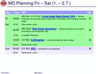
MD Planning Fri – Sat (1. – 2.7.). Long-range beam-beam MD. Some additional result: IR1 IR5 compensation… Test of tune working point close to half integer: 0.47. Reduction crossing angle IR1 (V) and IR5 (H). 12+36 b per beam 3.5 TeV beta*1.5m in IR1/5. Reduce IR5 angle.

E N D
MD Planning Fri – Sat (1. – 2.7.) MD Report
Long-range beam-beam MD Some additional result: IR1 IR5 compensation… Test of tune working point close to half integer: 0.47 MD Report
Reduction crossing angle IR1 (V) and IR5 (H) 12+36 b per beam 3.5 TeV beta*1.5m in IR1/5 Reduce IR5 angle Reduce IR1 angle 40% 35% 30% 50% 40% 35% 30% 40% 50 h 2 h Crossing angles in IR1 and IR5 reduced in steps of 5 – 10 %. TCT’s following changed orbit. 100% = 120 mrad = 12 sbeam-beam separation for e~2.5mm! 50% fine (no reduction in lifetime), 40% (5 s b-b) still OK, 30% too low! MD Report
IR1 Luminosity During IR5 Adjustments IR1 cross. angle at 48 mrad (~5s sep) constant. IR5 cross. angle being reduced. 72 mrad 60 mrad 48 mrad Luminosity 42 mrad 36 mrad Time Equal crossing angle amplitude in IR1/5 best for diffusion! Compensation of LR beam-beam effects in IR1 and IR5… MD Report
IR1 Luminosity During IR5 Adjustments IR1 cross. angle at 48 mrad (~5s sep) constant. IR5 cross. angle being reduced. 72 mrad 60 mrad 48 mrad Luminosity 42 mrad 36 mrad Maybe even smaller beam-beam separation is acceptable with equal amplitudes of IR1 and IR5 crossing angles!? Time Equal crossing angle amplitude in IR1/5 best for diffusion! Compensation of LR beam-beam effects in IR1 and IR5… MD Report
Tune WP Close to Half Integer (B1 shown) MD Report
Non-linear Dynamics MD (Dynamic Aperture) M. Giovannozzi et al • DA measurement part of the non-linear MD: • Correcting/checking tunes, coupling and chromaticity. • Aperture kicker was used to heat the beam and induce losses related to non-linear dynamics. • Intensity vs. time was recorded for: • nominal conditions (but with MOs set to zero) • scan on the MCOs strength • Originally it was also planned to scan over the MCDs strenght, but in the end it was not possible due to lack of time (mainly BETs issue at the SPS, which prevented to inject Beam 1 for a long time). • The data collected will need to be analysed off-line. MD Report
Non-linear Dynamics MD II F. Schmidt et al • NL chromaticity measurement and correction of Q" and Q"' with newly defined MCO & MCD spool piece: • In System/BETA-BEATING: • LHCBEAM/non_lin_chroma_dqq_b2 (b4) 1200.0 • LHCBEAM/non_lin_chroma_dqqq_b2 (b5) 160.0 • NL chromaticity B2 before correction: • Q" = -1800 570 (H/V) • Q"' = -1.900E6 0.78E6 (H/V) • NL chromaticity B2 after correction: • Q" = -670 -170 • Q"' = -0.37E6 -0.15E6 • Comments: • Collimation settings in IP6 limited the maximum kick strengths of both kicker types. Therefore no true DA measurement possible with kickers. • Spool piece correction very effective also to reduce detuning.with amplitude. MD Report
Non-linear Dynamics MD: Non-linear chromaticity (not corrected) MD Report
Non-linear Dynamics MD: Non-linear chromaticity (corrected) MD Report
Tune versus Action MD Report
Collimation MD • MD started at 17.00 (3 hours late) - due to delayed recovery from previous MD. • New alignment of collimators in IR3 for b1 and b2. • Centers of collimators within 100um from previous values, but for TCSG.5L3.B1 (230um difference) Excellent news! • In parallel, tested new automatic features of collimation application on B1. • Automatic alignment (not satisfactorily functioning yet). • Automatic pattern recognition of loss spikes. Worked for 98% of cases. 2% other cases: delay in detecting loss spike (under investigation)? MD Report
Collimation MD • Setup combined H betatron cleaning in IR3 for B2: • IR3 collimators moved to 5.7 (TCP),6.7 (TCSG),10 sigma (TCLA). • IR7 H and skew opened. IR7 V collimators left at relaxed settings. • Orbit correction on B2 before loss maps. • Test of system with B2 horizontal loss map • V and H tunes swapped. • Loss maps on B2 H betatron caused beam dump on both beams (TCLA.A5L3.B2). • Note that also TCTV in IR1 and IR8 were above dump thresholds (cleaning inefficiency ~ 1to 2%). • Cleaning inefficiency downstream IR3 (cold regions) 5e-4 • To be compared with simulations. MD Report
Collimator Settings B2 MD Report
Loss Map Combined H Betatron Cleaning 99.9 % MD Report
ATS MD (S. Fartoukh et al) • Two unsuccessful ramps (for various reasons), third fine. • Second ATS MD successfully demonstrated the principle: • beta*: 30 cm was reached at IP1 while • beta* IP5 remained to "pre-squeeze beta* of 1.2 m (already below existing collision beta* of 1.5 m). • Chromatic aberrations were well under control during the squeeze (non-linear chroma, off-momentum beta-beating). • The on-momentum beta-beating was recorded at beta*=4.4 m, 1.2 m, 54 cm and 30 cm. • At 30 cm: peak beta-beating error 15% - 40%, depending on plane and beam, with correction from empirical trims on Q2.R1, Q2.L5 and Q2.R5 (about 10-13 units), as derived for the nominal squeezed optics. • This beta-beating error has to be compared to the 400% design beta-beat induced on purpose in sectors 81 and 12 to squeeze beta* by a factor of 4w.r.t. the pre-squeezed beta* of 1.2 m. • Note: Pilot intensity Setup presently not usable for high intensity (collimation & MP issues). MD Report
ATS: 30 cm b* in IP1: Measured bx First time ever proof of principle for this optics solution MD Report
ATS: 30 cm b* in IP1: Measured by First time ever proof of principle for this optics solution MD Report
ATS: Measured Dispersion Error (here B2) MD Report
ATS: Off-Momentum Beta Beat Error (B2 H) MD Report
MD Planning Sun – Mon (3. – 4.7.) Needs from experiments: 30.6., 08:00 to 16:00 – Luminometers on in ATLAS and CMS 01.7., 18:00 to 02:00 – Luminometerson in ATLAS and CMS MD Report