Download
1 / 37
420 likes | 892 Views
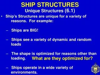
UNO Engineering Forum. September 19, 2014. Water Wave Impact on Ship Structures. Christine M. Ikeda, Ph.D . School of Naval Architecture and Marine Engineering Carolyn Judge. Sponsored by:. Outline.

E N D
UNO Engineering Forum September 19, 2014 Water Wave Impact on ShipStructures Christine M. Ikeda, Ph.D. School of Naval Architecture and Marine Engineering Carolyn Judge Sponsored by:
Outline Acknowledgements: Results shown from the United States Naval Academy were funded by ONR, and the project principal investigator was Carolyn Judge. Special thanks to the Hydromechanics Laboratory Staff at the United States Naval Academy: Dan Rhodes, Mark Pavkov, Bill Beaver, and John Zselecsky Hydrodynamic loading Ship Structure Structural Response A Hydrodynamics Point of View on the Slamming Impacts experienced by High-Speed Craft: Dynamic Pressures • Classical Wedge Drop Study Revisited • Tow-Tank Experiments on Planing Craft in Regular Waves Structural Response of Slamming Loads on High-Speed Craft: Full-Field Strain and Deflection Measurements • Classical Wedge Drop Study Revisited • Tow-Tank Experiments on Semi-Planing Craft in Regular and Irregular waves. Christine Ikeda 2
Slamming Impacts on High-Speed Marine Vessels Image courtesy of Combatant Craft Division (CCD) Little Creek Research Questions: • Is there a better way to design marine vehicles if we understand the physics of slamming events? • What happens if the bottom of the hull deflects? • How does the use of composites or aluminum in ship-building affect the physics and strength of the hull? Laboratory-scaled experimental studies seeking to provide insight into the physics of the slamming events • Slamming motions and forces are a function of wave topography, impact angle, forward speed, and body orientation during impact • Classic wedge drop experiment with new contributions:Spray Root and high-density pressure measurements • Tow-tank experiments on model-scaled planinghull in different wave conditions
Experimental Details • Acrylic wedge, constructed with 1.3-cm thick plates • Deadrise angle, β = 20° • Dimensions in cm • Length in and out of screen: 60 cm Drop heights ranging from 8 to 64~cm Tekscan Map PCB • Measurements: • Vertical Acceleration: Accelerometer • Vertical position: String Potentiometer • High-Speed Video:Phantom Miro M320S • Pressure on bottom surface High-speed camera • Point Measurements: PCB Piezotronics • Mapping System: Tekscan
Pressure Measurements Point-pressure sensors Single “sensel” or measurement point Field of View for High-speed Camera Pressure mapping system Bottom layout of pressure measurement locations 6 point pressure transducers Pressure mapping system (consists of an array of measurement points)
High-Speed Video New Contribution Video recorded at a speed of 4,000 frames per second and played back at 3 frames per second (1333 times slower than real life)
What was measured? P1 P2 P4 P3 P5 Keel Impact P6 Chine impact measured from videos C. Ikeda, and C. Judge. Impact Pressures and Spray Root Propagation of a Free-Falling wedge. Submitted to Experiments in Fluids, May 2014.
Similarity Solution 7.9 cm 31.8 cm 63.5 cm
Pressure Contours Christine Ikeda 10
Pressure Contours Christine Ikeda 11
Pressure Contours Christine Ikeda 12
Pressure Contours Christine Ikeda 13
Pressure Contours Christine Ikeda 14
Pressure Contours Christine Ikeda 15
Spray Root and Pressure Correlations Increasing Drop Height The lines show the computed spray root position versus time. The symbols show the position of the peak pressure versus time Christine Ikeda 16
High-Speed Craft Experiments performed at the United States Naval Academy
Experimental Facilities Dual flap, servo hydraulic control wavemaker Regular, irregular and transient waves; frequency range 0.3 to 1.4 Hz
Wave Characteristics Tow-speed: 6.4 m/s Bretschneider Spectrum to develop irregular wave model of a Sea State 3 Condition • 9.4 cm significant wave height • 1.7 s modal period Regular Wave field based on the most probable waves from Bretschneider Spectrum • Wave Height: 6.1 cm • Wave Period: 1.1 s
Planing Hull Characteristics • Fixed degrees of Freedom: • Sway, roll, yaw, surge (fixed to carriage) • Free in • Heave, Pitch
Measurements Accelerations • A1triaxial accelerometer (Heave, Sway and Surge) • A2 & A3 Heave (vertical accelerations only) Heave and Pitch measured at the LCG Incoming water surface (encounter wave) at 52 cm in front of the bow Wave Height elevation at 30.5 m from the wavemaker (fixed in tow tank)
Pressure Measurements Point – Pressure Transducers: • PCB Piezotronics Model 113B28 • Range: 344.7 kPa • Temperature effects mitigated with dielectric grease • No hydrostatic pressure reading Pressure Mapping System • Tekscan High-Speed Pressure Mapping System • Range: 690 kPa • Reads hydrostatic pressure
Tow-Speed: 6.4 m/s (12.4 knots), Regular WavesMovie Taken at 400 fps and played back at 10 fpsRun 44
Identification of Single Impact Use of acceleration-time histories to identify a single slam event • Free-fall or zero vertical acceleration followed by short duration high, upward acceleration from slam Heave, Pitch and Wave history • behavior consistent with the slam event characteristics Run 44
Single Impact Event (Run 44)Tow-Speed: 6.4 m/s (12.4 knots), Regular WavesMovie Taken at 400 fps and played back at 2 fps
Pressure Time History Run 44 Must assume that the planing motion is symmetric about the keel Point sensor measurement area: 24 mm2 • Sample Rate: 20kHz Sensel measurement area: 0.64 mm2 • Sample Rate: 730 Hz
Spatial Pressure Correlation Run 44 P23 P23 P22 P22 P21 P21 P21 P21 P22 P22 P23 P23
Spatial Pressure Correlation Run 44 P23 P23 P22 P22 P21 P21 P21 P21 P22 P22 P23 P23
Tow Speed: 9 m/s (17.5 knots), Regular waves2.4-m long modelMovie taken at 1400 fps and played back at 150 fps Christine Ikeda 29
Conclusions and Future Work Wedge Drop Experiment Novel method of quantifying the spray root propagation Pressure measurements correlate well with measured spray root propagation Calculated maximum velocity at impact and verification of similarity solution Understanding of the basic physics of these impact events can allow for the development of design tools and can aid in computer model validation High-Speed Planing Craft 146 total runs with about 15-20 impacts per run still a work in progress Analysis of pressure measurements show a discrepancy in pressure magnitudes between the two methods, but qualitatively look reasonable Isolating of individual slamming events using vertical acceleration data show there are different types of behavior based on how the ship hits the water surface, curvature of water surface
Structural Response Experiments to be performed at the University of New Orleans
Deflection of Ship Hull Bottoms Ghavami, K. and Khedmati, M.R., Finite Element Analysis - Applications in Mechanical Engineering, 2012 Image courtesy of Combatant Craft Division (CCD) Little Creek Why is this a concern? • Wide-spread use of composite materials in ship-building that are more likely to deflect • High-Speed craft slamming into large waves can severely injury passengers; consider an autonomous craft and focus shifts to not damaging the equipment on-board Research Questions: • How does the pressure-field in the fluid deform the structure? • How does the structure deformation affect the pressure field?
Deflection of Ship Hull Bottoms How can a ship be designed to take into account composite materials or deflections in the hull bottom? Conduct experimental study to determine the strength of the a composite deformable hull • Wedge drop study • Semi-planing study • Use of Digital Image Correlation (DIC) as an non-intrusive way to measure the full field strain on the structure • Use of Stereo DIC will allow for out-of-plane deflection • Continue to explore fluid dynamics of this problem in addition to the structural motions and deformation (What does the spray root behavior look like on high-speed craft?)
Classical Wedge Drop Study Revisited Camera 1 Camera 2 Spatial Correlation High-speed cameras t1 t1 t2 t2 Prismatic Wedges with thin-bottom plates: Aluminum Alloys and Composites Traditional measurements such as pressure, acceleration, heave Full-field strain measurements taken with Stereo- Digital Image Correlation to compute out-of-plane deflections Christine Ikeda 34
Semi-Planing Craft in Waves Scale-model hulls with thin-bottoms: Aluminum Alloys and Composites Traditional measurements such as pressure, acceleration, heave, pitch, roll Full-field strain measurements taken with Stereo- Digital Image Correlation to compute out-of-plane deflections Christine Ikeda 35
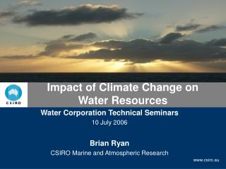
Final Remarks Off-Shore Wind Turbine Farm, Press-Release Photo from Siemens Off-Shore Wind Turbine Farm, Press-Release Photo from Siemens Image courtesy of Combatant Craft Division (CCD) Little Creek Fluid-Structure Interaction problems are present in many every-day applications. The physics of this interaction is interesting and can provide many new innovations/designs.
References Ikeda, C., Fluid–Structure Interactions: Implosions of Shell Structures and Wave Impact on a Flat Plate. PhD thesis, University of Maryland, College Park, August 2012.