EE 3563 Combinational Logic Design Practices
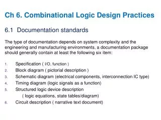
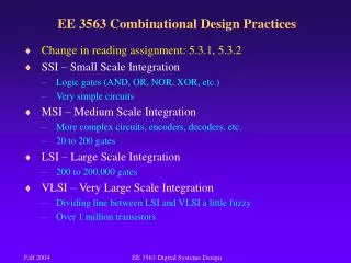
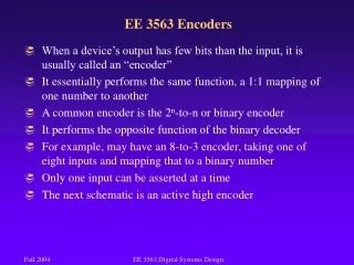
EE 3563 Combinational Logic Design Practices. Required Reading: 5.1, 5.2, 5.3, 5.4.1-5.4.5, 5.5.1-5.5.2, 5.6.1-5.6.2, 5.7.1-5.7.3, 5.8.1-5.8.4, 5.9.1-5.9.4, 5.10.1-5.10.7 Chapter 5.1 Documentation Standards We will only hit a few highlights of 5.1

EE 3563 Combinational Logic Design Practices
E N D
Presentation Transcript
EE 3563 Combinational Logic Design Practices • Required Reading: • 5.1, 5.2, 5.3, 5.4.1-5.4.5, 5.5.1-5.5.2, 5.6.1-5.6.2, 5.7.1-5.7.3, • 5.8.1-5.8.4, 5.9.1-5.9.4, 5.10.1-5.10.7 • Chapter 5.1 Documentation Standards • We will only hit a few highlights of 5.1 • You are required to read and know the rest • You may be tempted to just study these slides • I recommend that you DON’T EE 3563 Digital Systems Design
EE 3563 Chapter 5.1 Documentation Standards • 5.1.4 Active Levels for Pins • A signal may be active HIGH or active LOW. • Indicates when the signal’s function is taking place • A signal is “asserted” when it is in its active state • If a signal is active LOW, then it is asserted when it is LOW • A signal is “negated” or “deasserted” when it is not in its active state • Naming a signal with words can help clarify the functionality • What is the function of the circuit below? EE 3563 Digital Systems Design
EE 3563 Chapter 5.1 Documentation Standards • What is the function of this circuit below? • Bubble to Bubble logic design is the practice of choosing logic symbols and signal names, including active-level designators, that make the functionality of a circuit easier to understand EE 3563 Digital Systems Design
EE 3563 Chapter 5.1 Documentation Standards • Buses: • A bus is a collection of two or more related signal lines • Prominent examples are address and data busses in a microprocessor • Today we are primarily using 32-bit microprocessors (though 64 bit machines are available) • That number describes the size of the data that is processed in one step • The Pentium 4 has a 32-bit address bus and 128-bit data bus • Has a 4 Gigabyte address range • Can read 128 bits at one time from memory • Each bit is carried on a single “line” of metal, so there are 128 related lines, hence the term “bus” EE 3563 Digital Systems Design
EE 3563 Chapter 5.1 Documentation Standards EE 3563 Digital Systems Design