Download
1 / 17
200 likes | 437 Views
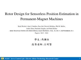
Rotor Design for Sensorless Position Estimation in Permanent-Magnet Machines Rafal Wrobel, Alan S. Budden, Dan Salt, Derrick Holliday, Phil H. Mellor, Andrei Dinu, Parmider Sangha, and Mark Holme IEEE TRANSACTIONS ON INDUSTRIAL ELECTRONICS, VOL. 58, NO. 9, SEPTEMBER 2011

E N D
Rotor Design for Sensorless Position Estimation in Permanent-Magnet Machines Rafal Wrobel, Alan S. Budden, Dan Salt, Derrick Holliday, Phil H. Mellor, Andrei Dinu, Parmider Sangha, and Mark Holme IEEE TRANSACTIONS ON INDUSTRIAL ELECTRONICS, VOL. 58, NO. 9, SEPTEMBER 2011 Page(s): 3815 - 3824 學生:馮謙詠 指導老師:王明賢
Outline 1.Abstract 2.Introduction 3. Design Considerations a. Manufacturing Considerations 4. FE Design a. FE Modeling b. Saliency Analysis 5.Conclusions 6.References
Abstract A high-frequency injection sensorless rotor position estimation algorithm is incorporated directly into the finite element design process to realize a permanent-magnet (PM) machine that is suited to zero- and low-speed sensorless control. The machine design is tightly constrained by an existing stator assembly, only enabling the redesign of the replacement PM rotor.
Introduction Sensorless position estimation in PM machines is reliant upon the existence of a measurable electrical parameter that is related to rotor position. When the machine is operating at speed, the electromotive force (EMF) generated across the machine supply terminals provides a suitable rotor-position dependent quantity . When the rotor is stationary or operating at low speed, however, no rotor- position-dependent parameter is readily available, and more complex methods that typically depend upon detection of the machine’s rotor dependent inductance profile are used . Typically, a PM machine may exhibit some degree of magnetic saliency which will cause a rotor-position-dependent variation in the inductance of the stator windings.
Design Considerations This machine comprises a concentrated wound stator with 1.5 slots per pole and a uniformly magnetized rotor with NdFeB magnet segments bonded to the surface of a magnetically permeable steel hub, as shown in Fig. 1. The interior PM (IPM) rotor topology exhibits more favorable saliency characteristics and was therefore chosen as the basis for the development of a new rotor. Fig. 1. Baseline concentrated wound surface magnet topology.
Manufacturing Considerations To simplify manufacture, the proposed rotor would use soft magnetic composite (SMC) pole pieces with rectangular PMs arranged in between a “spoke” pattern. The proposed rotor design is shown in Fig. 2, where the composite pole pieces and PMs are bonded to a nonmagnetic steel hub and the structure is secured using a thin sleeve. Fig. 2. Proposed IPM arrangement.
FE Design The manufacturing considerations described in Section 3-a dictate that torque and magnetic saliency are key design parameters. In addition, the predefined stator structure and air gap and the proposed rotor structure and materials limit the design variables to the depth and width of the rectangular magnet segments.
FE Modeling The magnet depth is expressed in terms of the ratio of the inner dimension to the outer radius , and the width is expressed as the ratio of an angle subtended by the magnet to the pole pitch , as shown in Fig. 2. These quantities are represented in the set of dimensionless parameters x, as shown in (7), which is used to specify the motor structure used in the FEM analysis Torque is calculated using the coenergy method shown in (8), where is the magnetic coenergy, Θ is the angle defining the relative position between the rotor and the stator, and ΔΘ is the angular rotation between field solutions (7)
FE Modeling Note that (10) is the inverse of the more usual definition of the saliency ratio and reflects the inverse saliency that is characteristic of the IPM machine Both the torque and saliency ratio calculations are repeated for different values of x, with target values of = 1 to ensure the correct torque performance and = 1.1, 1.2, 1.3, . . . , 2.5 to ensure a degree of rotor saliency that is suitable for sensorless control. The FE analysis incorporates an objective function, defined in (11), which seeks to minimize the error between the calculated and target values of torque and saliency (10)
FE Modeling Fig. 4 shows that, in general, the torque developed by the motor increases as (magnet width) increases and as (magnet depth) decreases. The saliency surface, shown in Fig. 5, is more complex and shows no simple trend in relation to changes to and .
FE Modeling Table I presents the target torque and saliency ratio values and the corresponding values resulting from the FE design process which are also highlighted on the surface plots of Figs. 4 and 5. It is important to note that the saliency ratios shown in Table I result from calculation at a fixed rotor position and that, beyond the limits of = 0.73 and = 0.93, none of the resulting rotor versions meets the design specification.
Saliency Analysis Fig. 9. Estimated rotor position for rotor version 1. Fig. 11. Estimated rotor position for rotor version 14.
Manufacture Of Rotor Version3 Fig. 14. IPM rotor version 3. (a) Rotor components. (b) Assembled rotor prior to the addition of the containment sleeve.
Conclusion A high-frequency injection sensorless position estimation algorithm has been directly incorporated into the FE design procedure for an IPM machine, resulting in a machine that exhibits the required electrical characteristics while being tailored for sensorless control. The design was highly constrained such that the rotor was required to fit within an existing stator and to produce the same torque as the original motor The experimental results verify the machine performance and operation under the control of an injection-based sensorless rotor position strategy.
References • [1] P. Acarnley and J. F. Watson, “Review of position-sensorless operation of brushless permanent-magnet machines,” IEEE Trans. Ind. Electron., vol. 53, no. 2, pp. 352–362, Apr. 2006. • [2] R. Wu and G. R. Slemon, “A permanent magnet motor drive without a shaft sensor,” IEEE Trans. Ind. Appl., vol. 27, no. 5, pp. 1005–1011, Sep./Oct. 1991. • [3] N. Matsui, “Sensorless PM brushless dc motor drives,” IEEE Trans. Ind. Electron., vol. 43, no. 2, pp. 300–308, Apr. 1996. • [4] L. A. de S. Ribeiro, M. C. Harke, and R. D. Lorenz, “Dynamic properties of back-EMF based sensorless drives,” in Conf. Rec. IEEE IAS Annu. Meeting, 2006, vol. 4, pp. 2026–2033. • [5] S. Bolognani, R. Oboe, and M. Zigliotto, “Sensorless full-digital PMSM drive with EKF estimation of speed and rotor position,” IEEE Trans. Ind. Electron., vol. 46, no. 1, pp. 184–191, Feb. 1999. • [6] A. Consoli, S. Musumeci, A. Raciti, and A. Testa, “Sensorless vector and speed control of brushless motor drives,” IEEE Trans. Ind. Electron., vol. 41, no. 1, pp. 91–96, Feb. 1994. • [7] O. Wallmark and L. Harnefors, “Sensorless control of salient PMSM drives in the transition region,” IEEE Trans. Ind. Electron., vol. 53, no. 4, pp. 1179–1187, Jun. 2006. • [8] P. L. Jansen and R. D. Lorenz, “Transducerless position and velocity estimation in induction and salient AC machines,” IEEE Trans. Ind. Appl., vol. 31, no. 2, pp. 240–247, Mar./Apr. 1995. • [9] O. Wallmark, L. Harnefors, and O. Carlson, “An improved speed and position estimator for salient permanent-magnet synchronous motors,” IEEE Trans. Ind. Electron., vol. 52, no. 1, pp. 255–262, Feb. 2005. • [10] S.-Y. Kim and I.-J. Ha, “A new observer design method for HF signal injection sensorless control of IPMSMs,” IEEE Trans. Ind. Electron., vol. 55, no. 6, pp. 2525–2529, Jun. 2008. • [11] M. J. Corley and R. D. Lorenz, “Rotor position and velocity estimation for a salient-pole permanent magnet synchronous machine at standstill and high speeds,” IEEE Trans. Ind. Appl., vol. 34, no. 4, pp. 784–789, Jul./Aug. 1998. • [12] F. M. L. de Belie, P. Sergeant, and J. A.Melkebeek, “A sensorless drive by applying test pulses without affecting the average current samples,” IEEE Trans. Power Electron., vol. 25, no. 4, pp. 875–888, Apr. 2010.
References • [13] J.-H. Jang, S.-K. Sul, J.-I. Ha, K. Ide, and M. Sawamura, “Sensorless drive of surface-mounted permanent-magnet motor by high-frequency signal injection based on magnetic saliency,” IEEE Trans. Ind. Appl., vol. 39, no. 4, pp. 1031–1039, Jul./Aug. 2003. • [14] S. Kondo, A. Takahashi, and T. Nishida, “Armature current based estimation method of rotor position of permanent magnet synchronous motor without mechanical sensor,” in Conf. Rec. IEEE IAS Annu. Meeting, 1995, vol. 1, pp. 55–60. • [15] C. Silva, G. M. Asher, and M. Sumner, “Hybrid rotor position observer for wide speed-range sensorless PM motor drives including zero speed,” IEEE Trans. Ind. Electron., vol. 53, no. 2, pp. 373–378, Apr. 2006. • [16] G. Foo and M. F. Rahman, “Sensorless sliding-mode MTPA control of an IPM synchronous motor drive using a sliding-mode observer and HF signal injection,” IEEE Trans. Ind. Electron., vol. 57, no. 4, pp. 1270– 1278, Apr. 2010. • [17] G. Foo and M. F. Rahman, “Sensorless direct torque and flux-controlled IPM synchronous motor drive at very low speed without signal injection,” IEEE Trans. Ind. Electron., vol. 57, no. 1, pp. 395–403, Jan. 2010. • [18] S. Sayeef, G. Foo, and M. F. Rahman, “Rotor position and speed estimation of a variable structure direct-torque-controlled IPM synchronous motor drive at very low speeds including standstill,” IEEE Trans. Ind. Electron., vol. 57, no. 11, pp. 3715–3723, Nov. 2010. • [19] A. S. Budden, R. Wrobel, D. Holliday, P. H. Mellor, and P. Sangha, “Zero speed sensorless position detection for permanent magnet synchronous machines,” in Proc. IEEE Power Electron. Spec. Conf., 2005, vol. 1, pp. 2436–2441. • [20] N. Bianchi, S. Bolognani, J.-H. Jang, and S.-K. Sul, “Advantages of inset PM machines for zero-speed sensorless position detection,” IEEE Trans. Ind. Appl., vol. 44, no. 4, pp. 1190–1198, Jul./Aug. 2008. • [21] N. Bianchi, S. Bolognani, J.-H. Jang, and S.-K. Sul, “Comparison of PM motor structures and sensorless control techniques for zero-speed rotor position detection,” IEEE Trans. Power Electron., vol. 22, no. 6, pp. 2466– 2475, Nov. 2007. • [22] N. Bianchi and S. Bolognani, “Sensorless-oriented design of PM motors,” IEEE Trans. Ind. Appl., vol. 45, no. 4, pp. 1249–1257, Jul./Aug. 2009. • [23] S. Wu, D. D. Reigosa, Y. Shibukawa, M. A. Leetmaa, R. D. Lorenz, and Y. Li, “Interior permanent-magnet synchronous motor design for improving self-sensing performance at very-low speed,” IEEE Trans. Ind. Appl., vol. 45, no. 6, pp. 1939–1946, Nov./Dec. 2009. • [24] J.-I. Ha, M. Ohto, J.-H. Jang, and S.-K. Sul, “Design and selection of AC machines for saliency-based sensorless control,” in Conf. Rec. IEEE IAS Annu. Meeting, 2002, vol. 2, pp. 1155–1162.
References • [25] N. Bianchi, S. Bolognani, and M. Zigliotto, “Design hints of an IPM synchronous motor for an effective position sensorless control,” in Proc. IEEE Power Electron. Spec. Conf., 2005, pp. 1560–1566. • [26] N. Bianchi and S. Bolognani, “Influence of rotor geometry of an interior PM motor on sensorless control feasibility,” IEEE Trans. Ind. Appl., vol. 43, no. 1, pp. 87–96, Jan./Feb. 2007. • [27] N. Bianchi, S. Bolognani, and A. Faggion, “Predicted and measured errors in estimating rotor position by signal injection for salient-pole PM synchronous motors,” in Proc. IEEE IEMDC, 2009, pp. 1565–1572. • [28] A. S. Budden, R. Wrobel, D. Holliday, P. H. Mellor, A. Dinu, P. Sangha, andM. Holme, “Impact of rotor design on sensorless position estimation,” in Proc. IEEE IECON, 2006, pp. 787–792. • [29] K. Yamazaki and H. Ishigami, “Rotor-shape optimization of interiorpermanent- magnetmotors to reduce harmonic iron loss,” IEEE Trans. Ind. Electron., vol. 57, no. 1, pp. 61–69, Jan. 2010. • [30] W. N. Fu, S. L. Ho, and Z. Zhang, “Design of position detection strategy of sensorless permanent magnet motors at standstill using transient finiteelement analysis,” IEEE Trans. Magn., vol. 45, no. 10, pp. 4668–4671, Oct. 2009. • [31] L. Harnefors and H.-P. Nee, “General algorithm for speed and position estimation of ac motors,” IEEE Trans. Ind. Electron., vol. 47, no. 1, pp. 77–83, Feb. 2000. • [32] Y. Kano, T. Kosaka, N.Matsui, and T. Nakanishi, “Design and experimental verification of a sensorless-oriented concentrated-winding IPMSM,” in Proc. XIX ICEM, 2010, pp. 1–6. • [33] M. W. Degner and R. D. Lorenz, “Using multiple saliencies for the estimation of flux, position, and velocity in ac machines,” IEEE Trans. Ind. Appl., vol. 34, no. 5, pp. 1097–1104, Sep./Oct. 1998. • [34] A. S. Budden, R. Wrobel, D. Holliday, P. H. Mellor, and P. Sangha, “Sensorless control of permanent magnet machine drives for aerospace applications,” in Proc. IEEE PEDS, 2005, vol. 1, pp. 372–377. • [35] D. Salt, D. Drury, and D. Holliday, “Compensation of nonlinear distortion effects for signal injection based sensorless control,” in Proc. IET PEMD, 2010, pp. 1–6. Thanks for your attention.