Download
1 / 26
260 likes | 291 Views
Learn about reducing beam impedances in accelerators by finding RF solutions and optimizing machine element geometry to enhance performance. Presentation by CERN BE-RF Group.

E N D
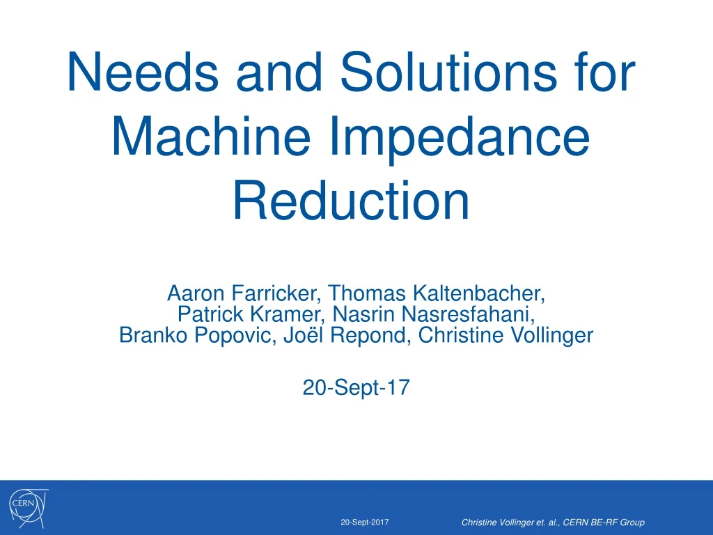
Needs and Solutions for Machine Impedance Reduction Aaron Farricker, Thomas Kaltenbacher,Patrick Kramer, Nasrin Nasresfahani, Branko Popovic, Joël Repond, Christine Vollinger 20-Sept-17 Christine Vollinger et. al., CERN BE-RF Group
Motivation for Impedance Reduction Christine Vollinger et. al., CERN BE-RF Group Highest possible beam intensities are requested today from most accelerators. These intensities can be reached only if the interaction of the particle beams with the surrounding structure is sufficiently low, and the contribution is known, at least approximatively. Consequently, a good description of the machine elements by means of impedances in the frequency domain or wake fields in the time domain is required to avoid performance limitations due to instabilities or other collective effects. Once the individual impedance contribution of a machine element is known, an optimization (geometrical or by means of mitigation) w.r.t. the contribution to beam impedance can be targeted.
Impedance Sources Christine Vollinger et. al., CERN BE-RF Group Usual approach is to calculate the contribution of separate machine elements, although in some cases this is insufficient, due to interaction/ coupling of the different elements. Generally to be distinguished between machine elements with potentially large individual impedance contribution as cavities, kickers, etc., and Other components with smaller individual contribution, but which exist in large quantities, as valves, flanges, pumping ports, general beam pipe transitions.
What this talk is about? Christine Vollinger et. al., CERN BE-RF Group Will not speak about instabilities and beam dynamic simulations, instead our work is to find RF-solutions to mitigate existing beam impedances, and to provide input for macroparticle codes by means of impedance calculation so that beam dynamics simulation can be carried out to predict, e.g., intensity thresholds, etc. Regular request for guidelines, thus a number of examples with possible mitigation strategies will be presented here.
Modeling of Machine Elements Christine Vollinger et. al., CERN BE-RF Group Geometry of the machine element has to be modeled such that its EM-behaviouris reproduced. Geometries that appear to be simple can be electromagnetically complex→ example:SPS vacuum flange shielding. It can easily come to “oversimplification”→ two examples:PS gate valve, andPS KFA45 kicker.
Example: SPS Vacuum Pipe Flanges • VFs of the SPS were not impedance optimized; • For the connection of different beam pipe shapes, a circular VF with bellows was selected at the time; • Some VFs additionally carry an enamel insulation on one side for DC-insulation. • Electromagnetically, this VF shapes a simple pill-box cavity with corrugated walls: Enamel MBA beam pipe(about rectangular) Unshielded VF Goal is to find a smooth transition for the different beam pipe shapes that shields this “pill-box cavity”. QF beam pipe(elliptical) Christine Vollinger et. al., CERN BE-RF Group
Example: SPS Vacuum Pipe Flanges Unshielded VF Shielding this “simple pill-box cavity” is non-trivial! Even with shields in place, a gap at the gasket position remains. Double-tube shield Spring-driven shield Braided shield gasket gasket Fixed RF fingers gasket gap filler gap filler gap filler Support with fixed RF contact Support with fixed RF contact Support with fixed RF contact Spring-driven moveable RF contact MBA beam pipe MBA beam pipe Shield made of stainless steel braid support plate support plate support plate Christine Vollinger et. al., CERN BE-RF Group
Example: SPS Vacuum Pipe Flanges Simulated longitudinal impedance Spring-drivenhield retro-fit from PP shield gasket gap closed • Without gasket gap filler, the resonance at about 1.4 GHz is not fully suppressed; • Otherwise, performance of the different shield designs is very similar! Christine Vollinger et. al., CERN BE-RF Group
Example: SPS Vacuum Pipe Flanges Unshielded VF [N. Ogiwaraet al., IPAC’13, Shanghai, THPFI014] • “state-of-the-art” nowadays are shields made of braids, where different materials and mesh structures are available from suppliers. • Braids of this type are also suggested for flexible connections in other locations. Christine Vollinger et. al., CERN BE-RF Group
Example: SPS Vacuum Pipe Flanges • VF shieldingisrequired, but is visible in beamdynamics simulations only, if othermeasures are applied at the same time (here: HOM damping of the 200 MHz TWC); • The improvementobtainedfrom VF shieldingthusdepends on the level of HOM reduction (e.g. factor 2 or 3) thatcanbereached; • Currently, we are targeting a HOM reduction for the 200 MHz TWC by a factor of 3.(see poster presentation of P. Kramer et.al. on Thursday!) 10% 15% Christine Vollinger et. al., CERN BE-RF Group
Modeling of Machine Elements Christine Vollinger et. al., CERN BE-RF Group Geometry of the machine element has to be modeled such that its main features are displayed. Geometries that appear to be simple can be electromagnetically complex→ two examples:SPS vacuum flange shielding, andSPS gate valves. It can easily come to “oversimplification”→ two examples:PS gate valve, andPS KFA45 kicker.
Example: PS Gate Valve Models Previous Impedance Model • No geometrical model of the inner parts of the valve exist; • Leaving these parts out will result in an entirely different impedance contribution; • Due to lack of geometry knowledge, measurements have to verify the correctness of the geometry. New (Longitudinal) Impedance Model Christine Vollinger et. al., CERN BE-RF Group
Example: PS Gate Valve ModelsComparing Measured & Simulation Results TE119 TE118 TE111 TE116 TE117 TE112 TE115 TE113 Cavity Mode TM010 1504.18 Q: 1184 TE114 TE115 1345.67 MHz Q: 1442 TE111 1207.04 MHz Q: 2352 Christine Vollinger et. al., CERN BE-RF Group
Example: PS Kicker KFA45 Previous Impedance Model New (Longitudinal) Impedance Model Christine Vollinger et. al., CERN BE-RF Group
Example: PS Kicker KFA45Comparing Wakefield Simulation Results for Different Modeling Also here: correctness of the modeling has to be verified by measurement ! Christine Vollinger et. al., CERN BE-RF Group
Example: Re-working a Machine “Section” in SPS • Request: • Insertion of an additional machine element in round beam pipe (left side). • New machine element has a beam pipe with race-track cross-section: Christine Vollinger et. al., CERN BE-RF Group
Example: Re-working a Machine “Section” in SPS + side view new machine element + top view Christine Vollinger et. al., CERN BE-RF Group
Example: Re-working a Machine “Section” in SPS • Example for bellows: • Identical bellows with entirely different EM-behavior due to connecting vacuum chambers. • Left: bellows resonates with circular part (BPCE & large, round beam-pipe)Right: bellows resonates but does not interact with adjacent machine elements due to cut-off frequency of flat, elliptical beam-pipe. Christine Vollinger et. al., CERN BE-RF Group
Example: Re-working a Machine “Section” in SPS elliptical bellows new machine element special bellows special bellows standard bellows BPCE Option 1: Original layout with one special bellows replaced by one elliptical bellows. vacuum chamber vacuum chamber vacuum chamber Christine Vollinger et. al., CERN BE-RF Group
Example: Re-working a Machine “Section” in SPS elliptical bellows new machine element special bellows special bellows standard bellows BPCE Option 1: Original layout with one special bellows replaced by one elliptical bellows. Gives a good indication for 850 MHz resonance source ! vacuum chamber vacuum chamber vacuum chamber Christine Vollinger et. al., CERN BE-RF Group
Example: Re-working a Machine “Section” in SPS new machine element BPCE elliptical bellows special bellows special bellows standard bellows Option 2: Original layout with special bellows replaced by elliptical bellows AND swap BPCE with new machine element. vacuum chamber vacuum chamber vacuum chamber Christine Vollinger et. al., CERN BE-RF Group
Example: Re-working a Machine “Section” in SPS new machine element BPCE elliptical bellows special bellows special bellows standard bellows Option 2: Original layout with special bellows replaced by elliptical bellows AND swap BPCE with new machine element, use a smooth taper after new element. vacuum chamber vacuum chamber vacuum chamber elliptical bellows Christine Vollinger et. al., CERN BE-RF Group
Example: Re-working a Machine “Section” in SPS new machine element BPCE special bellows special bellows standard bellows Option 3: Bring BPCE with its two bellows close to the QF-magnet, use a smooth taper and an elliptical bellows to connect new machine element. vacuum chamber vacuum chamber vacuum chamber Christine Vollinger et. al., CERN BE-RF Group
Example: Re-working a Machine “Section” in SPS new machine element BPCE elliptical bellows special bellows standard bellows Option 3: Although the cross-sectional changes appear to be reduced, AND a smooth taper is used, plus elliptical bellows, new resonances show upunexpectedly around 800 MHz and above 1 GHz. Conclusion: For beam impedance, Option 2 is by far the best re-arrangement ! + MDH vacuum chamber vacuum chamber smooth taper Christine Vollinger et. al., CERN BE-RF Group
Conclusion Christine Vollinger et. al., CERN BE-RF Group Powerful tools for impedance calculation exist today, but a careful geometrical modeling is absolutely required; Benchmarking of the geometry shall be done by EM-measurements, whenever possible; 1st goal should be to geometrically suppress the impedance source; If this is not possible, the remaining resonances/HOMs have to be taken out of the machine element (see e.g. poster of P. Kramer et.al. on Thursday); Guidelines are difficult to draw in a general manner (see three options for re-worked SPS machine section);
Thank you for your attention! Christine Vollinger et. al., CERN BE-RF Group