Download
1 / 46
460 likes | 666 Views
SEABROOK STATION RELIEF VALVE PROGRAM. PRDUG MEETING, ORLANDO, FLA. JANUARY 24-26, 2001. Roger Samson Bob Thomas Plant Engineering Maintenance. SEABROOK STATION RELIEF VALVE PROGRAM. Testing Video R. Samson / R. Thomas Program overview R. Samson

E N D
SEABROOK STATION RELIEF VALVE PROGRAM PRDUG MEETING, ORLANDO, FLA. JANUARY 24-26, 2001 Roger Samson Bob Thomas Plant Engineering Maintenance
SEABROOK STATION RELIEF VALVE PROGRAM • Testing Video R. Samson / R. Thomas • Program overview R. Samson • ORO-7 Code Revision R. Samson • Determination of testing parameters R. Samson • Test Equipment / Facility development R. Thomas • Data Package Revision For Hot Testing R. Thomas • ORO-7 testing results R. Thomas / R. Samson • EPRI Test Model R. Samson / R. Thomas • Questions and Answers R. Samson / R. Thomas Seabrook Relief Valve Team
Program Overview • Last plant using ASME XI, 1983 Edition, Summer Addenda No thermal relief valves TWO PARAGRAPHS - PTC 25.3 Bench test at ambient temperature • First plant using ASME O&M Code 1995 Edition, 1996 Addenda in its entirety Thermal relief valves now included Significant changes - prescriptive test requirements (Test media and ambient air temp requirements) Seabrook Relief Valve Team
SEABROOK STATION RELIEF VALVE PROGRAM • Program overview R. Samson • ORO-7 Code Revision R. Samson • Determination of testing parameters R. Samson • Test Equipment / Facility development R. Thomas • Data Package Revision For Hot Testing R. Thomas • ORO-7 testing results R. Thomas / R. Samson • EPRI Test Model R. Samson / R. Thomas • Questions and Answers R. Samson / R. Thomas Seabrook Relief Valve Team
New prescriptive test requirements: Class 1 RV’s and MSSV’s – 5 years, 20% min. in 2 yrs. Class 2&3 RV’s – 10 years, 20% min. in 4 yrs. .Additional scope if failure occur .Replacement Valves – special testing requirements. .Rupture Disks – replace every 5 years. Instrumentation ‑ 1% of setpoint. OR07 Code Revision Seabrook Relief Valve Team
OR07 Code Revision New prescriptive test requirements (con’t) • Testing Sequence:Visual, Leak, Setpoint, Leak, Bellows • Test Media same as operating, (e.g., steam, air, N2, water, oil, etc.). • Test Media Temperature & Ambient Temperature Operating vs. conditions when valve is expected to actuate • Thermal Equilibrium Criteria, (10F change in 30 minutes) • 10 Minutes between Lift Tests • 2 Consecutive Lifts, (without adjustment) • Alternate Test Media Correlation. Seabrook Relief Valve Team
Significant Changes Test Media Temperature & Ambient Temperature - • Expected to perform its intended function • These conditions also apply to Seat Tightness. • Requires test equipment with “Hot” testing capabilities. Seabrook Relief Valve Team
Significant Changes (con’t) Alternate Test Media Correlation • Permits testing using both cold ambient and media conditions provided that correlation test data exists to support cold testing. • Some vendors had media correlation • No vendors combined media and ambient temperature • No vendors had ambient temperature correlation • Some vendors refused to do alternate media testing Seabrook Relief Valve Team
SEABROOK STATION RELIEF VALVE PROGRAM • Program overview R. Samson • ORO-7 Code Revision R. Samson • Determination of testing parameters R. Samson • Test Equipment / Facility development R. Thomas • Data Package Revision For Hot Testing R. Thomas • ORO-7 testing results R. Thomas / R. Samson • EPRI Test Model R. Samson / R. Thomas • Questions and Answers R. Samson / R. Thomas Seabrook Relief Valve Team
Determination of testing parameters Temperature Requirements - two methods: • Normal system operating Versus • Conditions when valve is expected to perform its function upset system or emergency accident condition what function each valve was performing what conditions were associated with its function Document search included Technical Specifications, UFSAR, System Calculations and technical (T/P) sheets Seabrook Relief Valve Team
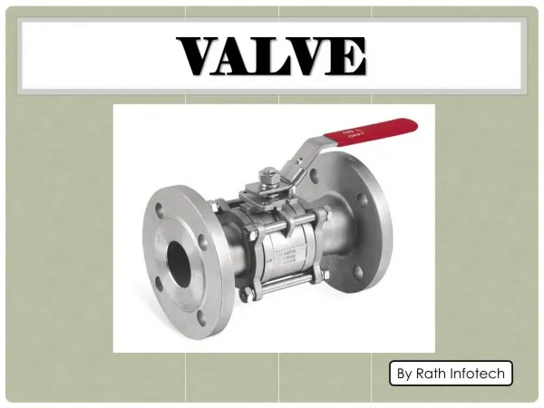
Test valve Seabrook Relief Valve Team
SEABROOK STATION RELIEF VALVE PROGRAM • Program overview R. Samson • ORO-7 Code Revision R. Samson • Determination of testing parameters R. Samson • Test Equipment / Facility development R. Thomas • Data Package Revision For Hot Testing R. Thomas • ORO-7 testing results R. Thomas / R. Samson • EPRI Test Model R. Samson / R. Thomas • Questions and Answers R. Samson / R. Thomas Seabrook Relief Valve Team
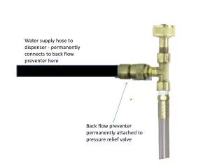
Test Equipment / Facility Development Seabrook Relief Valve Team
Test Equipment / Facility development • Design Considerations • SAFETY • VOLUME CONTROL • TEMPERATURE CONTROL • ERGONOMIC OPERATOR CONTROLS Seabrook Relief Valve Team
SAFETY Due to the increased energy potential created by flashing fluids, special safety features were included in the equipment and facilities design. Seabrook Relief Valve Team
SAFETY RCA TEST STAND Due to radiological release concerns, the RCA test stand discharge system includes an adjustable, sealed discharge pipe for each table and a vented discharge tank. The tank is equipped with a sparging system and has provisions for connection of a HEPA filter, if required. COLD SIDE TEST STAND The cold side test stand discharge system includes an adjustable, sealed discharge pipe and an exhaust pipe vented to atmosphere through the side of the building. Seabrook Relief Valve Team
SAFETY Quick Acting Valves Quick acting air operated valves were added on the accumulator and table vent lines This allows for rapid venting if the pressure increases in the test stand due to internal flashing. Quick acting air operated valves were also added on the accumulator / table isolation valves in case of a stuck open valve. Seabrook Relief Valve Team
Test Equipment / Facility development • Design Considerations • SAFETY • VOLUME CONTROL • TEMPERATURE CONTROL • ERGONOMIC OPERATOR CONTROLS Seabrook Relief Valve Team
VOLUME CONTROL Manual bypass valve on water side Bypass line on the water circuit allows for low volume set pressure testing on smaller valves or when lifting larger valves is undesirable. Three rates of air feed to accumulator lets the operator vary the fill rate and air volume from air storage to accumulator. Three rates of air feeds to the accumulator Seabrook Relief Valve Team
VOLUME CONTROL Restricting Devices Valves are often partially gagged to restrict lift and conserve heated water. Seabrook Relief Valve Team
Test Equipment / Facility development • Design Considerations • SAFETY • VOLUME CONTROL • TEMPERATURE CONTROL • ERGONOMIC OPERATOR CONTROLS Seabrook Relief Valve Team
TEMPERATURE CONTROL Separate Heat Zones Vessel, piping, and environmental chambers are divided into seperate heating zones for variable heat control. Local Controllers Each heat zone has a local controller to program final temperature settings, and ramp rates Seabrook Relief Valve Team
Test Equipment / Facility development • Design Considerations • SAFETY • VOLUME CONTROL • TEMPERATURE CONTROL • ERGONOMIC OPERATOR CONTROLS Seabrook Relief Valve Team
ERGONOMIC OPERATOR CONTROLS Seabrook Relief Valve Team
ERGONOMIC OPERATOR CONTROLS Cold Side Test Stand Control Panel Because of the extended testing duration's, sit down control panels were used on both hot and cold side testers. All controls are within easy reach of operator. Valves, pressure gauges, switches and heating controllers are all accurately positioned on the tester’s schematic “mimic”. Seabrook Relief Valve Team
ERGONOMIC OPERATOR CONTROLS Seabrook Relief Valve Team
ERGONOMIC OPERATOR CONTROLS Seabrook Relief Valve Team
ERGONOMIC OPERATOR CONTROLS Seabrook Relief Valve Team
SEABROOK STATION RELIEF VALVE PROGRAM • Program overview R. Samson • ORO-7 Code Revision R. Samson • Determination of testing parameters R. Samson • Test Equipment / Facility development R. Thomas • Data Package Revision For Hot Testing R. Thomas • ORO-7 testing results R. Thomas / R. Samson • EPRI Test Model R. Samson / R. Thomas • Questions and Answers R. Samson / R. Thomas Seabrook Relief Valve Team
Data Package Revision For Hot Testing Seabrook Relief Valve Team
SETPOINT VERIFICATION / DATA ACQUISITION SETPOINT VERIFICATION Seabrook Relief Valve Team
SETPOINT VERIFICATION / DATA ACQUISITION SETPOINT VERIFICATION Seabrook Relief Valve Team
SETPOINT VERIFICATION / DATA ACQUISITION SETPOINT VERIFICATION Seabrook Relief Valve Team
SETPOINT VERIFICATION / DATA ACQUISITION Cold SideTester Piping Hot Side Tester Piping Seabrook Relief Valve Team
SETPOINT VERIFICATION / DATA ACQUISITION Seabrook Relief Valve Team
SETPOINT VERIFICATION / DATA ACQUISITION Seabrook Relief Valve Team
SETPOINT VERIFICATION / DATA ACQUISITION Seabrook Relief Valve Team
SETPOINT VERIFICATION / DATA ACQUISITION Seabrook Relief Valve Team
SETPOINT VERIFICATION / DATA ACQUISITION Seabrook Relief Valve Team
SEABROOK STATION RELIEF VALVE PROGRAM • Program overview R. Samson • ORO-7 Code Revision R. Samson • Determination of testing parameters R. Samson • Test Equipment / Facility development R. Thomas • Data Package Revision For Hot Testing R. Thomas • ORO-7 testing results R. Thomas / R. Samson • EPRI Test Model R. Samson / R. Thomas • Questions and Answers R. Samson / R. Thomas Seabrook Relief Valve Team
OR07 Test Results • New Scope thermal relief valves - near 100% • One LER - RH Suction Relief Valve lifted low • Expanded scope for several groups Containment Component Cooling system • 2 Rupture Disc replaced • Oil tests - DG System Seabrook Relief Valve Team
OR07 Test Results Seabrook Relief Valve Team
OR07 Test Results Seabrook Relief Valve Team
OR07 Test Results Seabrook Relief Valve Team
SEABROOK STATION RELIEF VALVE PROGRAM • Program overview R. Samson • ORO-7 Code Revision R. Samson • Determination of testing parameters R. Samson • Test Equipment / Facility development R. Thomas • Data Package Revision For Hot Testing R. Thomas • ORO-7 testing results R. Thomas / R. Samson • EPRI Test Model R. Samson / R. Thomas • Questions and Answers R. Samson / R. Thomas Seabrook Relief Valve Team
EPRI Test Model Shortly after our facility was declared operational EPRI was invited for a facility tour and demonstration. After the visit EPRI requested that Seabrook run a series of tests at various combinations of fluid and ambient temperatures. Seabrook agreed to perform the testing which was completed in late November. The plan involved 60 lifts, 10 at each set of ambient and fluid temperatures. The first three tests will evaluate fluid temperature effects alone. The next two (when combined with the first) will evaluate the effects of ambient temperature alone. The final test when compared to the first will evaluate the combined effects of fluid and ambient temperature increases. By conducting 10 lifts at each test condition we will obtain excellent statistical confidence in the observed mean values from each data set. EPRI will begin the development of the thermal model with the intention of predicting the set point changes resulting from the testing described above. Based on the results of this effort, EPRI will be able to develop a cost effective research plan for validating the model for the full range of class 2 and 3 relief valve designs in use in the industry. In addition, the data obtained will provide very significant insights into the effects of fluid and ambient temperatures on relief valve set points. Seabrook Relief Valve Team