Download
1 / 23
490 likes | 3.16k Views
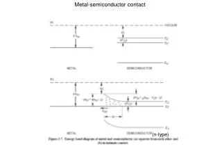
Contact Resistance Measurement Techniques between Metal and Semiconductor Interface

E N D
Contact Resistance Measurement Techniques between Metal and Semiconductor Contacts- Part-A Ajaya Kumar Kavala Reg No:0921PH01 Department of Physics
Content of My Seminar • Ohmic Contact: practical perspective • What is the Contact resistance? • Different types of measurement techniques • Conclusions
Ohmic Contact :practical perspective • Ohmic Contact could have linear or quasi-linear current voltage characteristics but what is essential: it must be able to supply necessary device current and the voltage drop should be small, and • Contact should not degrade the device and should not inject minority carriers
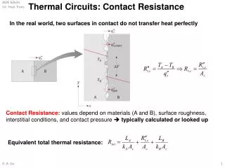
Contact resistance • The term contact resistance refers to the contribution to the total resistance of a material which comes from the two material contact (metal-semiconductor) and electrical leads, which is an inherent property, independent of the measurement method
Various Geometry of Contact Vertical Horizontal(Lateral) • Vertical and horizontal (lateral) contacts can behave quite differently, because contact area may differ from true contact area.
A Rough Method for Measuring Contact Resistance of a Semiconductor: Two probe lateral contact on a diffused semiconductor layer Total Contact Resistance RT = 2Rm + 2Rc + Rsemi Rm=Resistance of the metallic conductor Rc= Contact Resistance Rsemi=Semiconductor resistance
How to characterize Contact resistance of different areas and geometry? Specific Interfacial Resistivity (Theoretical) It depends on barrier height and interfacial doping density. • For Practical purpose: • ρc=Specific Contact resistivity is for real contacts their measurements and measurements interpretations , ( m2) • It is independent of contact area and is convinent parameter when comparing contacts of various sizes A → 0
Measurement techniques Contact resistance measurement techniques fall into four categories 1.Two -contact Two –Terminal 2.Multiple –Contact two –Terminal 3.Four-Terminal Contact resistance method 4.Six -Terminal Contact resistance method
Two-Contact Two-Terminal Method • Contacts on the Top surface • RT =Rc+ Rsp+Rcb+Rp • Rc = Contact resistance of the top contact • Rsp= The spreading resistance in the Semiconductor • Rcb =The Contact Resistance of the bottom contact • Rp= The Probe Resistance • The Bottom contact usually has a large contact area with a small resistance
Two-Contact Two-Terminal method • The spreading resistance can be defined in the following expression Rsp = ρ/2r×arctan(2t/r) r = Circular top contact radius t = Thickness ρ = Surface of a Semiconductor resistivity • For 2t >> r Rsp= C × ρ/4r where C is Correction Factor that depends on the ρ, r, and on the current distribution .R.H. Cox and H. Strack, “Ohmic Contacts for GaAs Devices,” Solid-State Electron. 10, 1213–1218, Dec. 1967.
Two-Contact Two-Terminal Method • The Current flowing vertically into the top contact for that contact resistance is(Correction factor C=1) Rc = ρc/Ac = ρc/r2 For very small Rcb. Rc=RT - Rsp The Two Terminal method works best when Rsp << Rc
Lateral Two terminal contact geometry The Two terminal method is more commonly implemented with lateral structure. Shown below are side and top views. • Total ResistanceRT=Rshd/W+2Rc
Multiple Contact Two terminal methods • To overcome the deficiencies of the two contact two terminal method • Three identical contacts are made to the semiconductor with contact spacing d1 and d2 • Total contact resistance RTi= Rshdi/ W+2Rc Where i=1 or 2 for Rc Rc= (RT2d1-RT1d2)/2(d1-d2)
Multiple-contact Two-Terminal methods • Identical Contact resistance for all three contacts is some what questionable but is reasonable for not too large sample. • The determination of lengths d1 and d2 is source of inaccuracy (Negative contact resistance). • An early Two dimensional current flow analysis by Kennedy and Murley in diffused semiconductor resistors ,That revealed current crowding at the contacts
Transfer Length Method • When current flows from the semiconductor to metal, it encounters the resistances ρc and Rsh • The Potential distribution under the contact • The Transfer length is H.H. Berger, “Models for Contacts to Planar Devices,” Solid-State Electron. 15, 145–158, Feb. 1972; H.H. Berger, “Contact Resistance and Contact Resistivity,” J. Electrochem. Soc. 119, 507–514, April 1972.
Transfer Length: Physical Significance • 1/e distance of the voltage curve is defined as the transfer length • The transfer length can be thought of distance over which most of current transfer from semiconductor into metal and vice versa Potential under a contact versus x as a function of ρ , where x= 0 is the contact edge L=10 𝝁m,Z=50𝝁m and Rsh=10𝜴/square
Transfer length method • Transfer length method can be divided into Two categories 1. Front contact resistance tests structure 2. Cross bridge Kelvin resistance Structure
Front contact resistance tests structure • In This method W = Z has been assumed. • With V measured Contacts 1 and 2 at x = 0 The contact front resistance can be expressed as
Circular transfer line structure W ≠ Z Can be avoided with circular test structures It consists a conducting circular inner region of radius L , a gap of width d and a conducting outer The total contact resistance between the internal and external contacts Where I and K denotes the modified Bessel functions of the first order For L >> 4LT I0/I1→1 and K0/K1→1 S.S. Cohen and G.Sh. Gildenblat, VLSI Electronics, 13, Metal-Semiconductor Contacts and Devices, Academic Press, Orlando, FL, 1986, p. 115; G.S. Marlow and M.B. Das, “The Effects of Contact Size and Non-Zero Metal Resistance on the Determination of Specific Contact Resistance,” Solid-State Electron. 25, 91–94, Feb. 1982; M. Ahmad and B.M. Arora, “Investigation of AuGeNi Contacts Using Rectangular and Circular Transmission Line Model,” Solid-State Electron. 35, 1441–1445, Oct. 1992
Circular transfer line structure C is correction factor C=L/dln (1+d/L) For d/L <<1 Circular contact resistance test structure )
Cross bridge Kelvin resistance Structure • The Voltage is measured at right angles to the current • In this method the voltage contact 3 is located at the side of contact • Voltage is the linear average of the Potential over the contact length L • The Contact resistance is Rc=V/I=ρc/LZ
Conclusion 1.Ohmic contact and Contact resistance will be mainly concerned with metal-semiconductor contacts because they are most common. 2.From the Two Terminal-Two Contact we cannot overcome the crowding current 3.From Two terminal-multiple contact we can not avoid the high current density(Degradation the device)