Download

1 / 35
410 likes | 757 Views
7 th OpenFOAM workshop, Technische Universität Darmstadt, Germany 25-28 June, 2012. Consideration on heat and reaction in metal foam. 2012. 6. 26 Mino Woo, Changhwan Kim and Gunhong Kim. Kyungwon Engineering & communication Inc., S. Korea. Contents . Motivation

E N D
7thOpenFOAM workshop, TechnischeUniversität Darmstadt, Germany 25-28 June, 2012 Consideration on heat and reaction in metal foam 2012. 6. 26 Mino Woo, Changhwan Kim and Gunhong Kim Kyungwon Engineering & communication Inc., S. Korea
Contents • Motivation • Porous model review • porousSimpleFoam • Porous model modification • Flow analysis • Derivation of porous model parameter • Thermal analysis • Comparison micro scale analysis to porous model approach • Ongoing topic • Apply surface reaction on micro structure
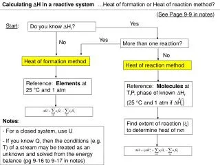
Motivation • Multi-scale consideration for analyzing phenomena within a porous media • Research subject Reference : Micro-Scale CFD Modeling of Packed-Beds, Daniel P. Combest, 6thOpenFOAM Workshop Derive porous model parameters (Permeability, Quadratic drag factor) Validation and Reproduction (a) Micro foam model (b) Porous model
porousSimpleFoam • Governing equation where, Linear resistance of pressure due to the permeability Non-linear resistance due to the quadratic drag factor In case of homogeneous porous media(Isotropic), Reference : Porous Media in OpenFOAM, HaukurElvarHafsteinsson, Chalmers spring 2009
porousSimpleFoam • Setting porous model parameters • constant/porousZones porous { coordinateSystem { e1 (1 0 0); e2 (0 1 0); } Darcy { d d [0 -2 0 0 0 0 0] (2.5e10 2.5e10 0); f f [0 -1 0 0 0 0 0] (700 700 0); } } Direction vector for defining local coordinate system Porous model parameters for each direction
porousSimpleFoam • Validation • Test case : channel flow • Geometry • Mesh • Hexagonal type, 50X200 (#10000) • Operating condition • Reynolds number = 250 2 m Wall Outlet Inlet Porous zone 0.25 m Symmetry 0.5 m Reference : Flow Through Porous Media, Fluent Inc. [FlowLab 1.2], April 12, 2007
porousSimpleFoam • Test case and results Reference : Flow Through Porous Media, Fluent Inc. [FlowLab 1.2], April 12, 2007
Porous model modification • Physical velocity formulation • Continuity • Momentum equation Porosity(γ) : measure of the void spaces in a material, and is a fraction of the volume of voids over the total volume, between 0–1 Superficial velocity (seepage velocity) Physical velocity (true velocity) porosity • Pressure drops are equally calculated from each model. • Physical velocity formulation is more realistic to analyze heat and mass transfer phenomena within porous media Modified model porousSimpleFoam porousSimpleFoam Modified model
Porous model modification • Comparison Porosity = 0.5 Original porousSimpleFoam (Superficial velocity formulation) Modified porousSimpleFoam (Physical velocity formulation) • Pressure drops are same, but inner velocities are different from each model
Porous model modification • Axial velocity distribution Comparison the results of axial velocity distribution between physical velocity formulation andsuperficial velocity formulation Comparison with commercial CFD software(CFD-ACE+, ESI) • In the porous part, result of superficial velocity formulationdiffers from the result of physical velocity formulation; the difference is 1/γ times • The result from commercial software is almost same as OpenFOAM result.
Porous model modification • Fluid phase enthalpy equation hEqn.h fvScalarMatrixhEqn ( fvm::div(phi, h) - fvm::Sp(fvc::div(phi), h) - fvm::laplacian(turbulence->alphaEff(), h) == - fvc::div(phi, 0.5*magSqr(U), "div(phi,K)") ); pZones.addTwoEquationsEnthalpySource(thermo, gamma, ts, hEqn); hEqn.relax(); hEqn.solve(); thermo.correct(); Interfacial heat and mass transfer
Porous model modification • Solid phase enthalpy equation where, a : specific surface area (1/m) h : heat transport coefficient (W/m2-K) Interfacial heat and mass transfer tsEqn.h fvScalarMatrixtsEqn ( -fvm::laplacian(kappa,ts) ); pZones.addTwoEquationsTsSource(thermo, gamma, ts, tsEqn); tsEqn.relax(); tsEqn.solve();}
Metal Foam • Characteristics • High specific stiffness, surface area and low pressure drop • Possibility to operate efficiently at higher space velocity compared to traditional flow-through substrates • Application • After-treatment system(DPF, DOC etc.,) • Heat exchanger • Catalytic reactor(SMR, LNT etc.,) • Foam manufacturer • STL geometry from 3D scanning • Pure Nickel foam before alloying and sintering process is used • Isotropic structure(Not compressed)
Mesh generation • Geometry cleaning • High resolution 3D scanning provides the basic STL geometry • STL contains both box boundary and inner foam structure • All surfaces are merged, and boundaries are unclearly • Hard to define foam surface Internal shape Face shape Original STL geometry
Mesh generation • Surface extraction • Pre-meshing to extract only foam structure • Need to clean up for small volume or skew cells • Smeared by surface mesh size easy to mesh for fluid domain • Fluid domain mesh • Reference case (mesh# = 304,794) • Meshes depend on the size of foam Meshed STL surface Fluid domain mesh of reference case
Operating condition • Computational domain(reference case) • Extend fluid domain back and forth from micro structure • Calculate the pressure drop with respect to inlet velocity 1.5L L 1.5L symmetry Outlet Inlet(air) Rep=20~2000 (a) Micro scale analysis symmetry Porous zone Outlet Inlet(air) Rep=20~2000 (b) Porous model
Operating condition • Test case • Foam width dependency • Effects on width normal to the flow direction • Foam length dependency • Effects on length along the flow direction Reference size Increase foam width Increase foam length 2x 4x 8x Width dependent cases Length dependent cases
Micro scale analysis • Results (Repore ~ 20 ) (a) velocity vector (b) pressure Velocity and pressure distribution within micro structure
Micro scale analysis • Width dependency Relationship between Reynolds number and pressure drop by changing width of porous media • Pressure resistance rising non-linearly upon the increasing flow speed. • Pressure drop though porous media is independent of their width Effect of width of porous media on the pressure distributions(1, 2, 4 and 8 times width), Repore ~20
Micro scale analysis • Length dependency Effect of length of porous media on the pressure distributions(1, 2, 4 and 8 times width), Repore ~20 Relationship between Reynolds number and pressure drop by changing length of porous media • Non-linear pressure resistance of increasing velocity • Pressure drops gradually rise up with increasing length of porous media • Darcy-Forchheimer equation Derive permeability and quadratic drag factor from above P-V plot
Porous model • Reference case (a) velocity vector (b) pressure Velocity and pressure distribution of porous model result for reference case • Total pressure resistance is similar to micro scale analysis, but internal fields of velocity and pressure are quite different. • Pressure within porous part is gradually decreased along the length of porous media because pressure drag term is uniformly applied to the porous part
Porous model • Comparison Comparison between porous model results and micro scale results : Effect of pressure drop on the length of porous media and Reynolds number • Porous model can predict pressure drop which is almost same as results of micro scale because porous model parameters are derived from micro scale results • Although internal field cannot be predicted by porous model, it is useful to calculate pressure drop between porous media
Analysis of derived model parameters • Derived K, CF in terms of length • Derivation of model parameters is conducted in two different conditions • The model parameters are conversed to certain value by increasing length • In this case, change of model parameters is below 1% at 0.004 mm condition(10 times to the pore size)
Conjugate heat transfer • combining mesh mappedWall boundary (chtMultiRegionSimpleFoam) solid domain Fluid domain • Interface meshes share the information through mappedWall boundary condition. • Interface meshes need not completely equal because the mappedWall calculates the value using interpolation. • Mesh mismatches are found locally in final mesh. Local mesh mismatches
Operating condition • Conjugate heat transfer • Analyze heat transfer characteristics in various velocity condition 1.5L L 1.5L symmetry Inlet(air) 1~20m/s 293.15K Outlet Wall : 323.15K (a) Micro scale analysis symmetry Inlet(air) 1~20m/s 293.15K Porous zone Wall : 323.15K Outlet (b) Porous model
Micro scale analysis • Temperature distributions (a) Inlet velocity : 1m/s (b) Inlet velocity : 5m/s (d) Inlet velocity : 20m/s (c) Inlet velocity : 10m/s Fluid and solid temperature distributions with changing inlet velocity(1,5,10 and 20) • Heat is transferred from each side of wall to the center through solid, and it is transferred to fluid region. • Heat transfer rate is changed by flow residence time.
Porous model • Fluid temperature (a) Inlet velocity : 1m/s (b) Inlet velocity : 5m/s (d) Inlet velocity : 20m/s (c) Inlet velocity : 10m/s Fluid and solid temperature distributions with changing inlet velocity(1,5,10 and 20) • Temperature fields are fairly similar to the results of micro scale analysis • Porous model also shows the effect on residence time
Comparison • Outlet temperature • In some condition, porous model predict micro scale results well, but it’s not all conditions. • Additional study on interfacial heat transfer coefficient will be conducted to enhance heat transfer performance of porous model
Results • CO-O2 binary reaction test CO+0.5O2 CO2 A= 3.70e+21(cgs), Ea=105KJ/mol • Reaction takes place in the near cell from the interface in fluid domain • Based on chtMultiRegionSimpleFoam (a) CO (reactant) (b) CO2 (product) (d) Velocity magnitude (c) temperature
Future work • Light-off curve(conversion rate) Validation case Now researching Conversion characteristics of ongoing reaction model • Now we are studying reaction characteristics using micro structure analysis • To develop surface reaction solver of metal foam using porous model concept. Reference : From light-off curves to kinetic rate expressions for three-way catalyst M.Matthess et al., Topics in Catalysis Vols. 16/17, Nov 1-4,2001
Thank you for your attention Email : minowoo@kwenc.kr